DISCLAIMER: this page is just my build log and a collection of notes. It is not a step-by-step guide on how to build the device. If you want to build something like this, you can freely use the information here but be prepared to do a lot of research and testing on your own.
I've always been a big fan of small portable computers/gadgets with proper hardware keyboards. So at some point I decided it would be fun to make something like that. My main use case for a device like this is flashing and debugging some embedded device in the field without the need to bring my laptop.
Note: this article will go through the build process and some interesting details. For those who aren't interested in details, the summary of used components and the code/3D models are at the end of the article.
Note: I did a talk about this at DORS/CLUC 2019 conference. Slides are available at https://bit.ly/hgtermslides and video will be available in a week or so.
EDIT 2019-05-08: here's the talk from the DORS/CLUC2019 conference: https://www.youtube-nocookie.com/watch?v=_vco84tjuYo
2019-05-14: this page got featured on Hackaday.com: https://hackaday.com/2019/05/14/this-is-the-raspberry-pi-mini-laptop-that-we-want 2019-05-16: got featured on Liliputing: https://liliputing.com/2019/05/hgterm-converts-a-raspberry-pi-into-a-versatile-handheld-computer.html 2019-05-16: got featured on ZDNet: https://www.zdnet.com/article/using-raspberry-pi-and-a-3d-printed-case-this-guys-made-a-slick-mini-laptop/
Table of Contents
Hardware
Since this should be a device for field use I had some requirements:
- long battery life (at least 5-6 hours)
- reasonable performance
- power management (shutdown, battery charging, battery monitoring)
- high resolution touch screen
- hardware keyboard
- GPIOs, analog inputs, serial port
- "stand mode" where display can be opened up to 270°
- SD card reader (TODO)
- proper sound (TODO)
There are many similar projects to this one (most notably NODE terminal and NanoPi2 UMPC) but they don't really fit the requirements listed above (mainly due to the small battery and lack of I/O).
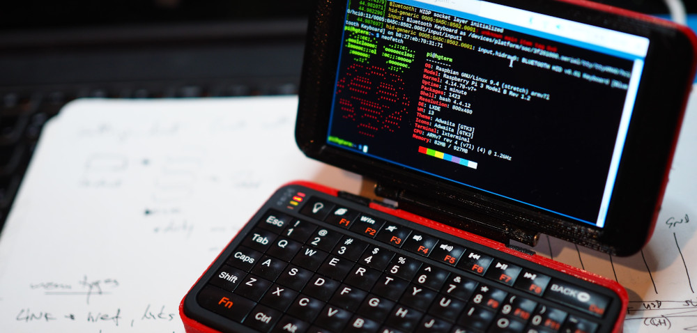
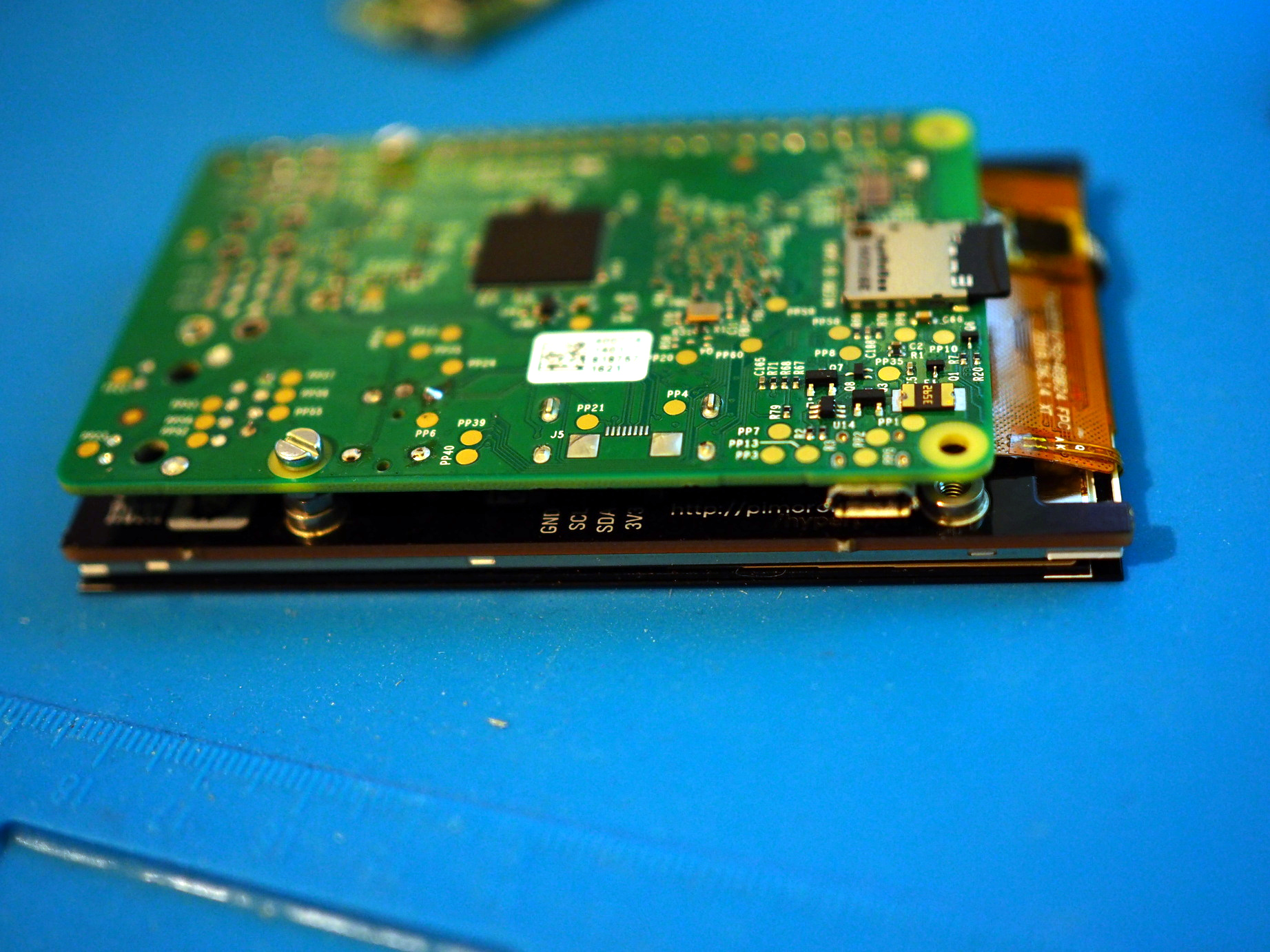
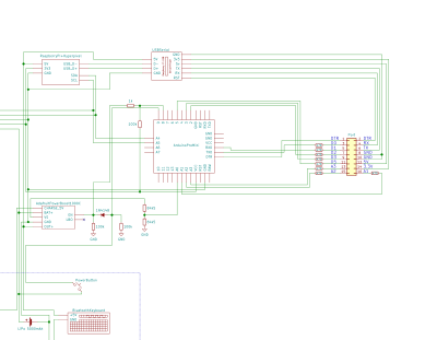
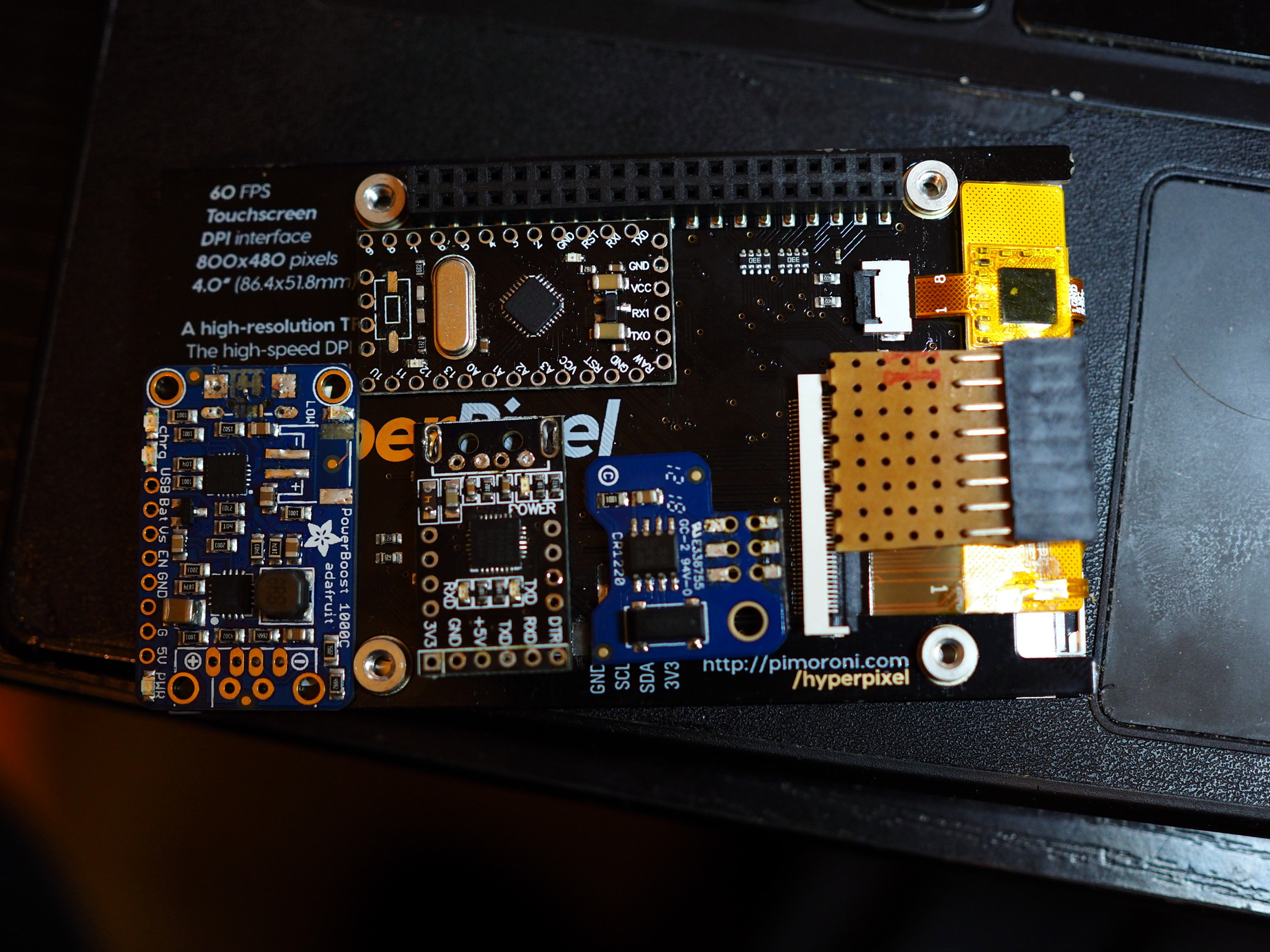
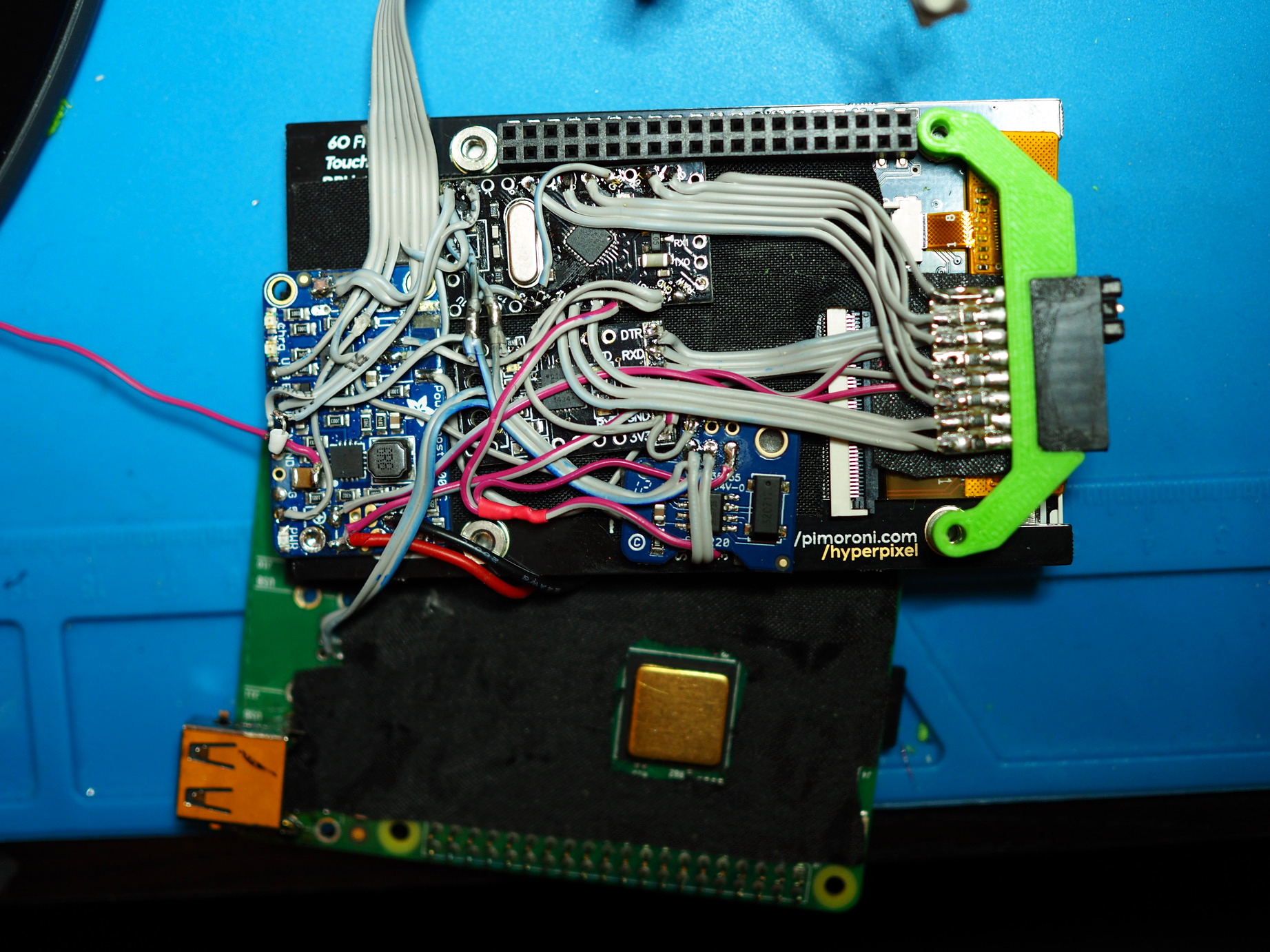
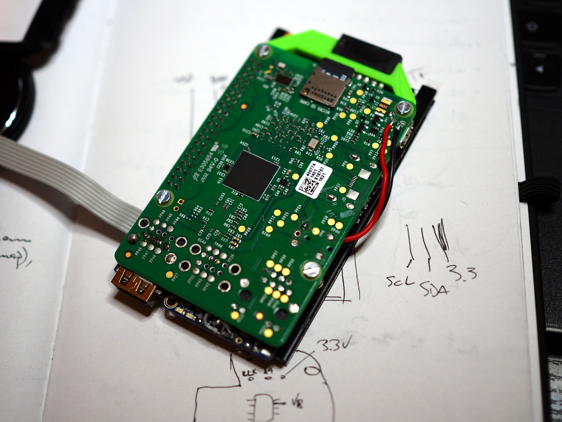
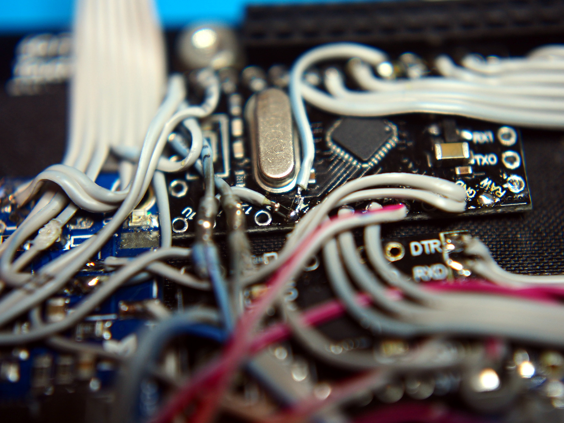
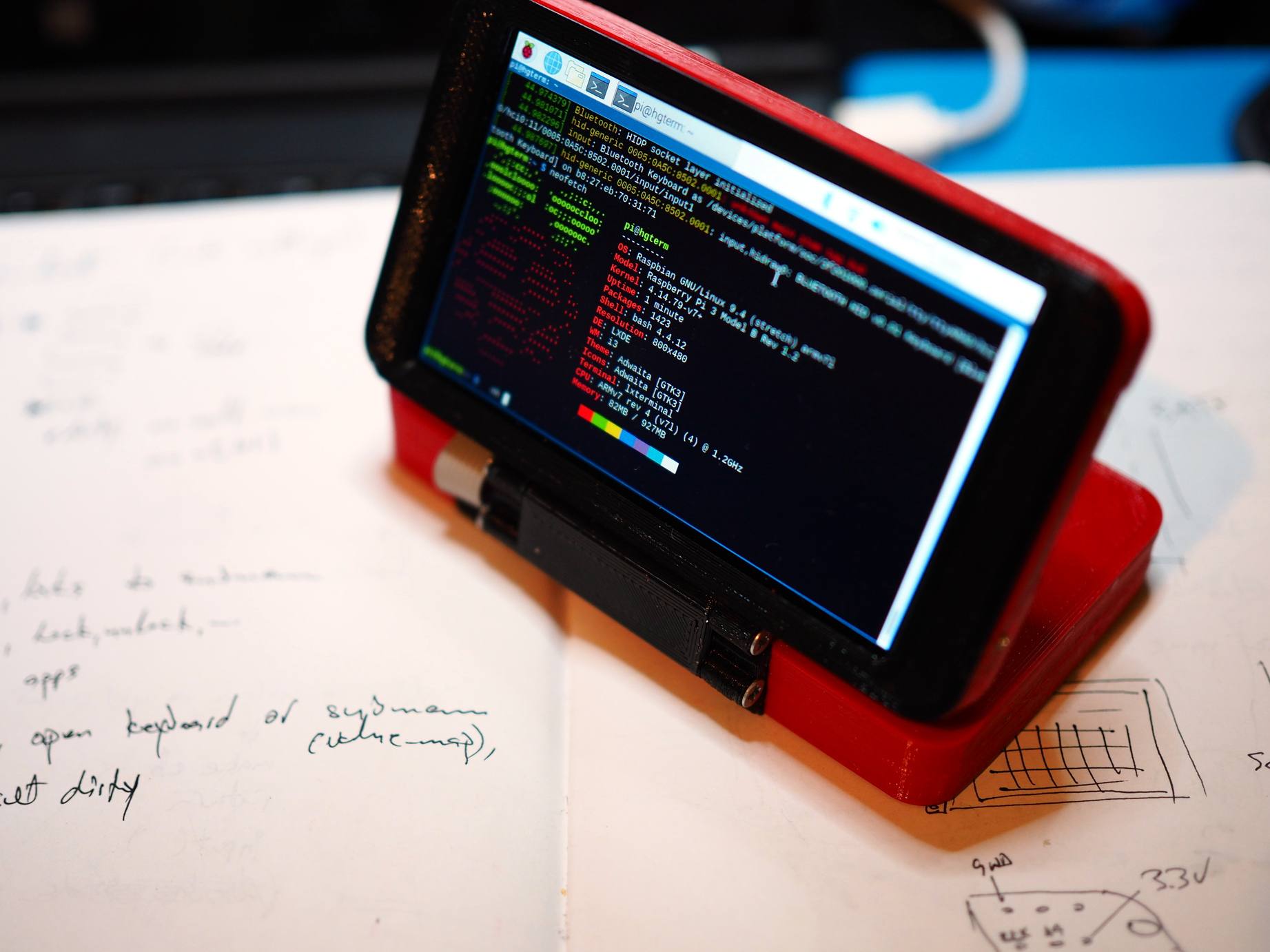
For the display I chose Pimoroni's Hyperpixel4, 4" display with capacitive touch and 800x480 resolution. The screen looks beautiful but it takes pretty much all of the Raspberry's GPIO pins. The good thing is that it exposes one I2C bus which can then be used for GPIOs. The first idea was to add an I2C port expander and ADC but I realized that a better option would be to add an Arduino board inside which would handle power management, GPIOs and analog inputs as an I2C slave device which I can query from Pi. That, together with USB-serial converter, would cover the I/O needs. Display connects to Pi's GPIO port directly which means that Pi will go to the device's "lid" and bottom part will contain battery and keyboard.
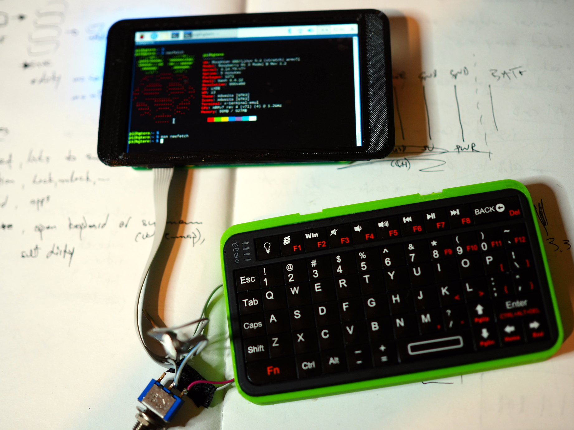
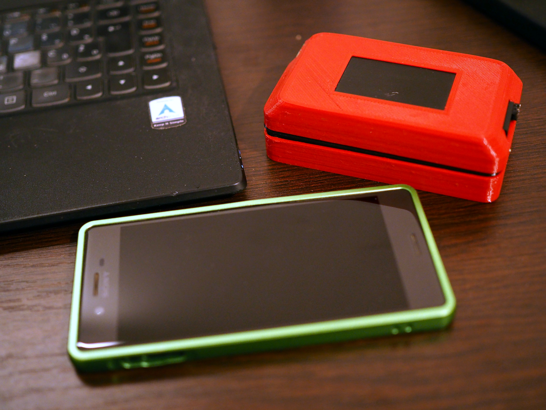
For keyboard I went with small Rii bluetooth keyboard I found on Aliexpress as it has all the standard keys (Ctrl, Alt, Meta, function keys, ...) and backlight. The good thing (which is also a bad thing) is that since it is wireless it only requires power to work. But it will often go into the power saving mode and takes few seconds to wake up. I had an idea to attach a microcontroller directly to keyboard matrix but that would be a whole project by itself. Also, there is an unpopulated pin header on the keyboard PCB which might be used to re-flash the onboard controller – I should investigate it at some point.
Here we can see the display, Raspberry Pi, keyboard (with battery underneath it), an RTC circuit (Adafruit PiRTC), Arduino Pro Mini and power management board.
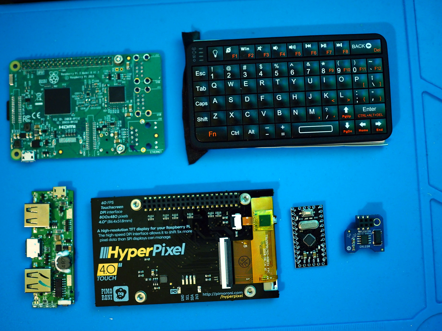
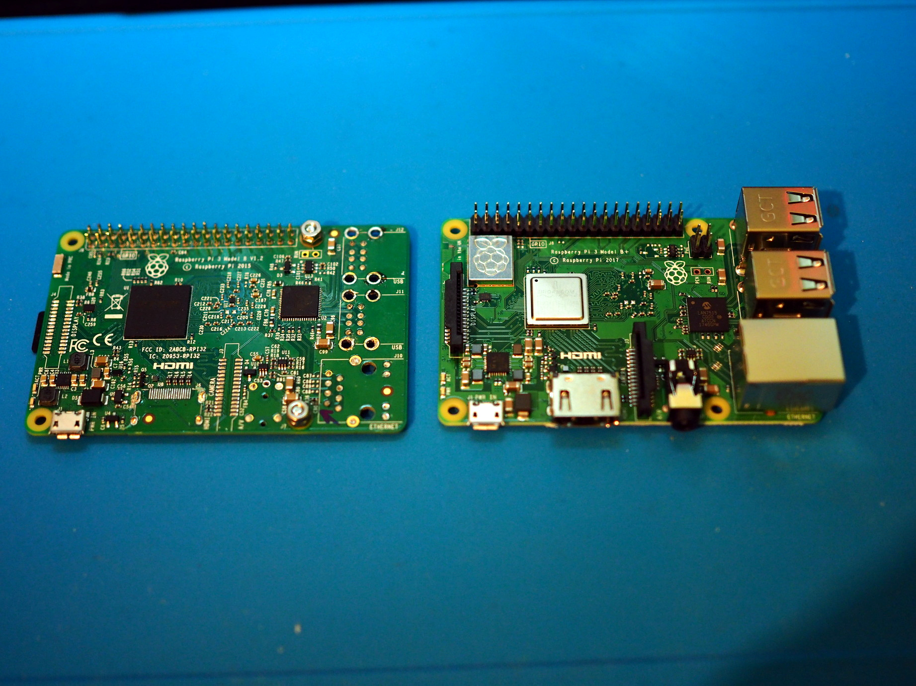
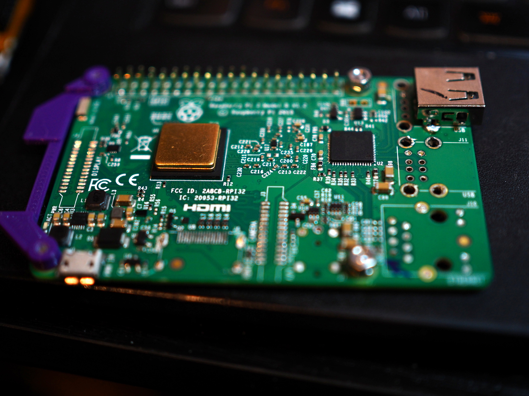
I decided to go with Raspberry Pi 3 board. Using Raspberry Pi Zero would save a lot of space but the performance would be awful. Going with 3B+ would increase performance a bit but at the expense of higher power usage.
To make everything as small and as tightly packed as possible, the Pi had to be "prepared". This means everything that takes up space (and isn't needed) goes away: USB ports (we'll have only one), ethernet port (WiFi is enough and USB-ethernet can be plugged if needed), HDMI (only one display can be active at a time), camera and display connector (don't need them) and audio connector (onboard sound is terrible, TODO: add USB sound card). I even cut the GPIO pins to some 60% and removed the plastic which holds header pins.
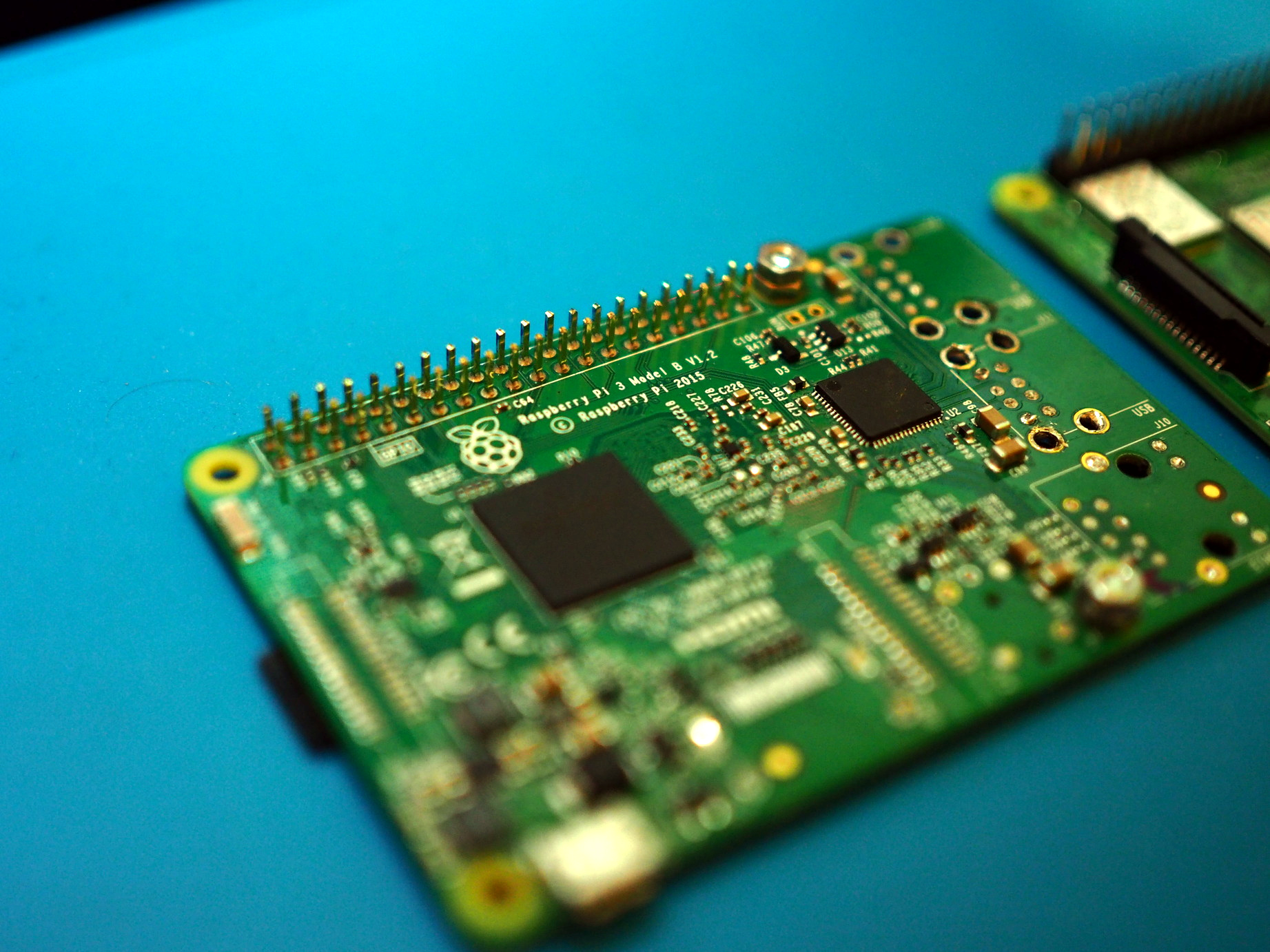
All of that was done to make the display fit as close as possible to the Pi and the final result was some 5mm of space between the two (ignoring the height of components). And this is the space where everything else should fit.
Power
The power supply was an interesting story. At first I planned to use a powerbank – I had a Canyon 4000mAh powerbank which had a four LED status indicator and a power key for which I figured out how it could be triggered from the Arduino board (for cutting off the power). It also had some unneeded features like fast charging. So, to get everything as small as possible I started cutting away the "unneeded parts". In the picture below everything was still working and I should've stopped at that point. But I haven't.
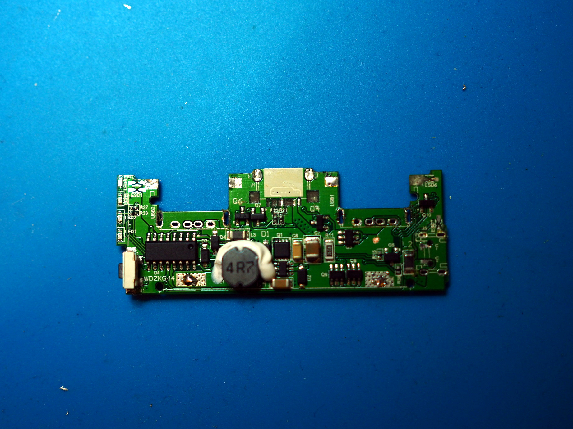
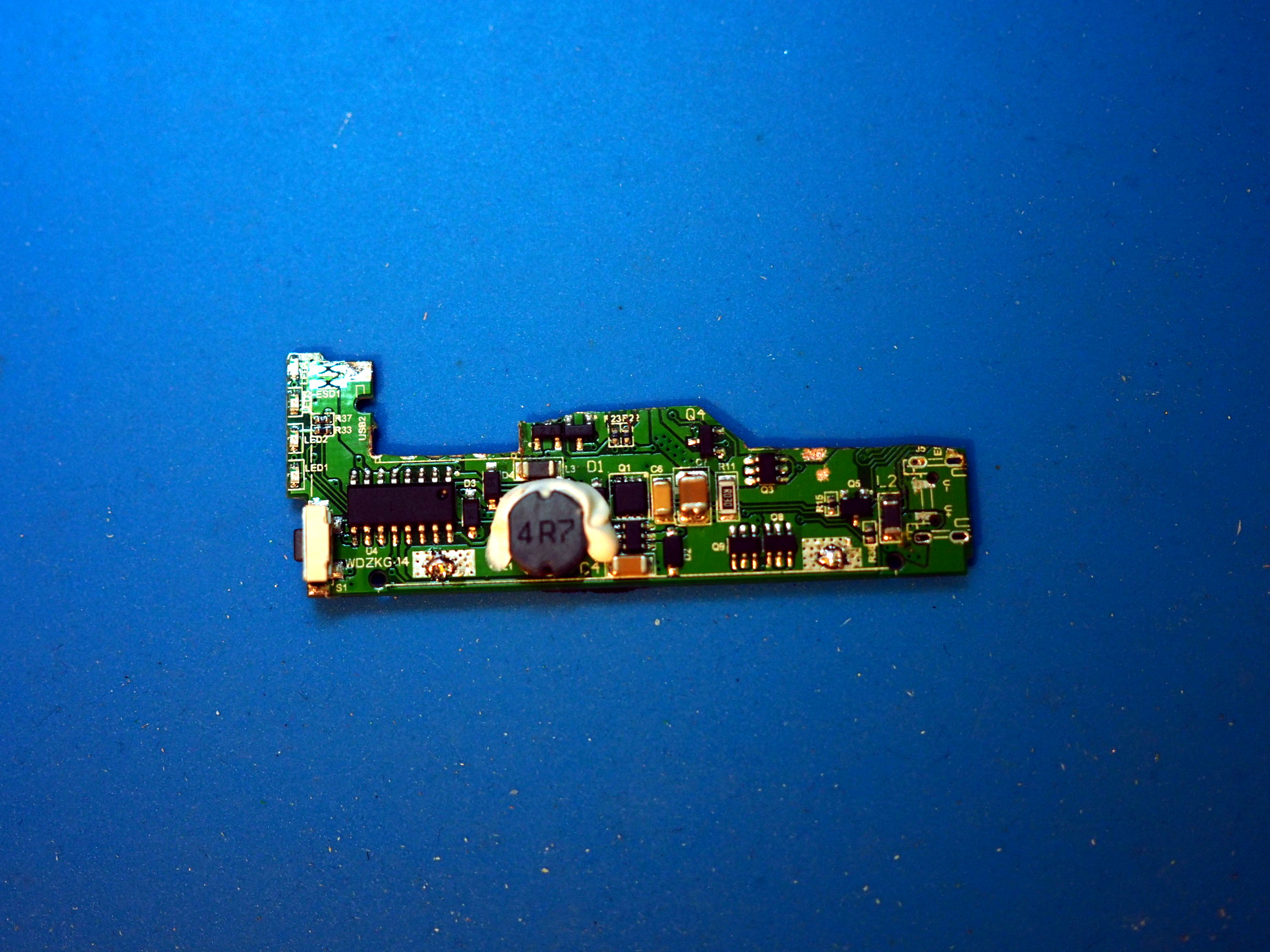
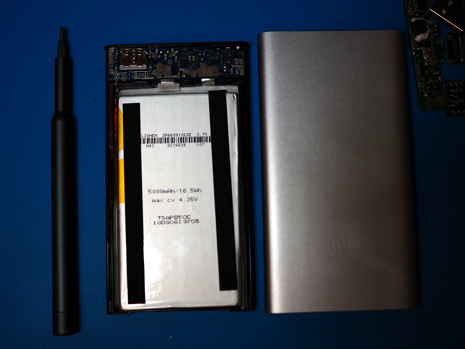
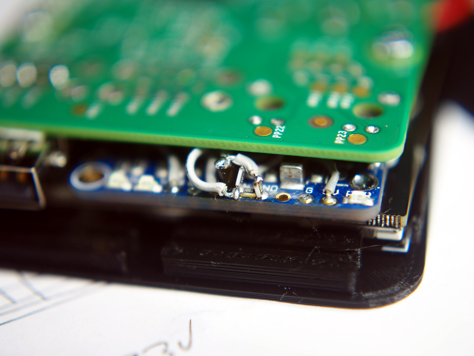
Next try was with Xiaomi 5000mAh powerbank which had the same looking features (LED indicators and a power button) but it turned out the button isn't useful for cutting the power as it powered on again as soon as it detected there is even slight power draw. But the battery from this powerbank was really nice (5000mAh and just a little bit smaller than the keyboard) so I decided to use it in the build. For the power management board in the end I went with Adafruit's Powerboost 1000C (which I should've done immediately).
Using Kicad I made a schematic of the connections inside. Power management part was inspired by lipopi project but with a few differences. When the power button is pressed it connects Powerboost's enable input to the battery which enables the Powerboost board. EN pin is pulled high to arduino board's power supply but the pin 8 can be used to pull it low and turn it off. Pin 9 is used to detect the state of the power button so that the shutdown procedure can be triggered when the key is pressed but also the "hard poweroff" (in case Pi isn't responding) can be done by holding the power button for a few seconds.
Fitting everything
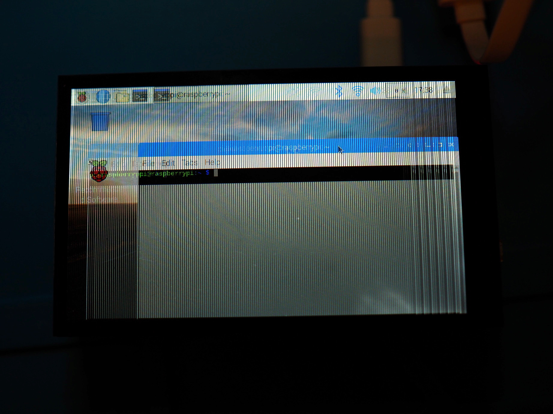
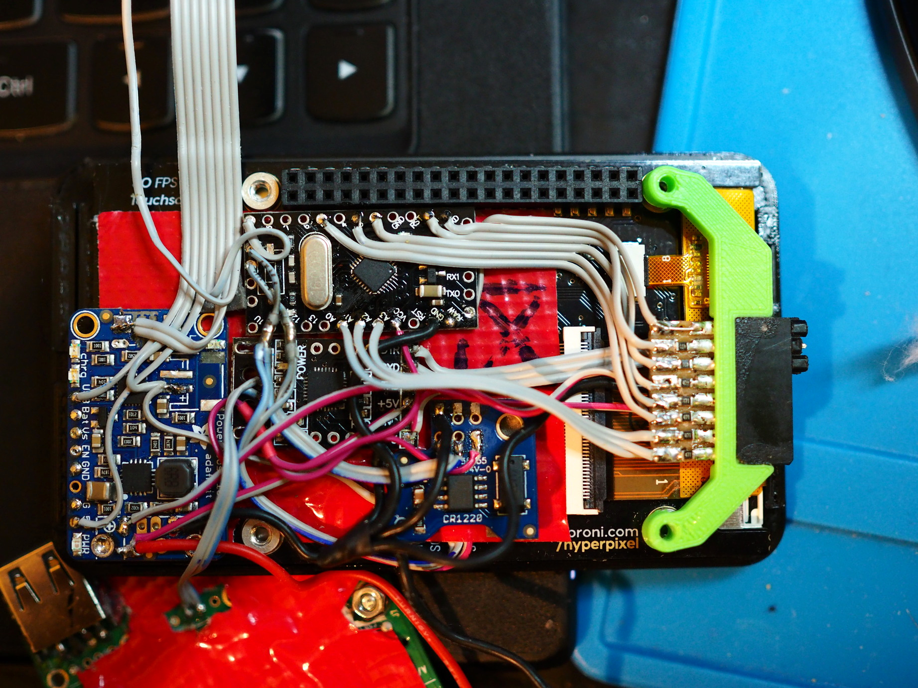
When trying to fit a bunch of small boards (Powerboost, RTC, arduino, USB-Serial) in the space between Pi and display, one quickly realizes it's actually not that easy – small boards need to be carefully placed at the right positions so they don't collide with components on the Pi board. This required a lot of the display dettach-attach cycles and resulted in damaged screen (I think I damaged the flat cables at one point). On the other side, now that the screen was broken I could test everything in a more relaxed manner and, when everything works, just put in a working screen (easier said than done :)).
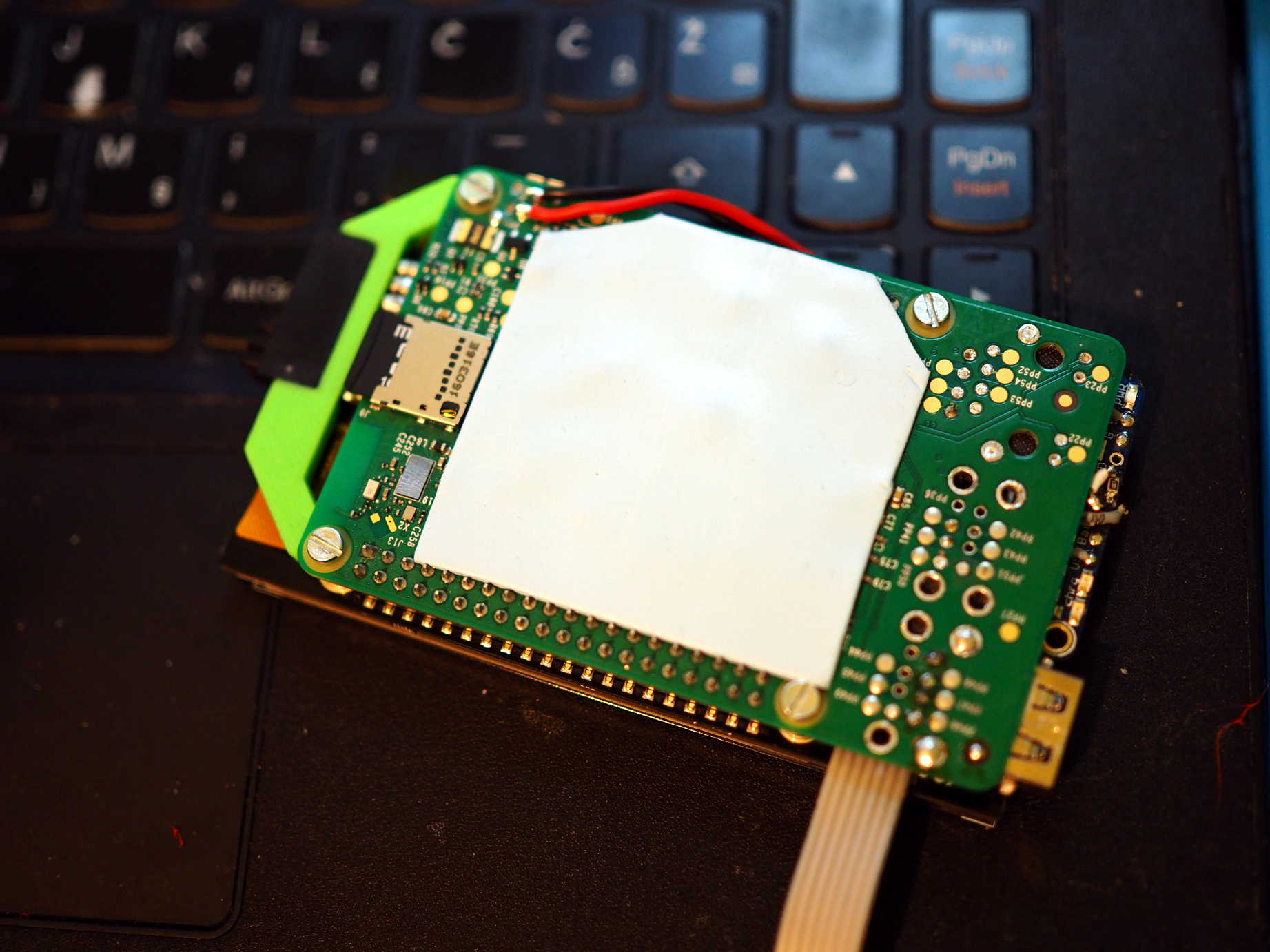
Thermal
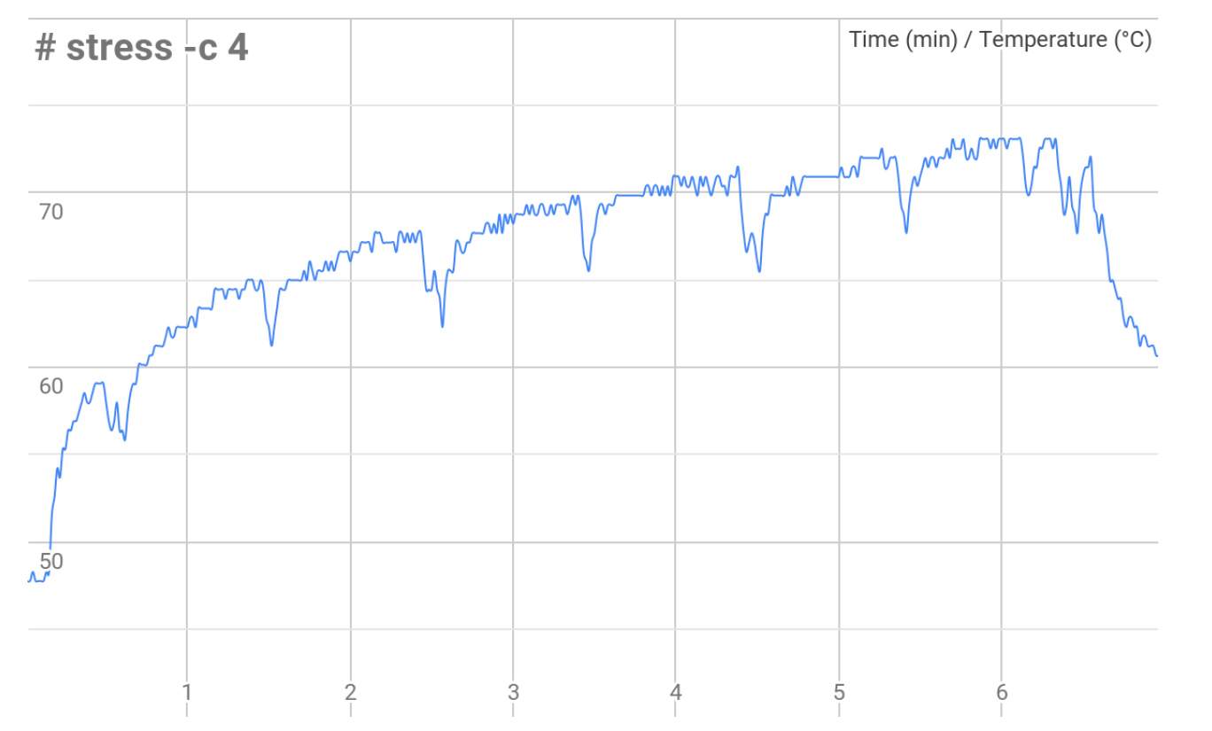
One important thing to consider is the thermal management. When loaded, Pi tends to heat up quite well and that heat somehow needs to be removed from it. In a local electronic store called Chipoteka I found small copper heatsinks with adhesive on one side and mounted two of them onto the main CPU. But, since there will be no air flow inside the enclosure this only increased the thermal capacity but didn't handle the cooling. So I decided to add an alluminum plate on the other side of the Pi and thermally "connect" it to the Pi using thermally conductive pad (ARCTIC thermal pad). The image below shows temperature rise across six minute when all four cores are fully loaded (while the enclosure is closed). We see that it gets to about 73°C and stays there which isn't perfect but it's good enough.
Testing
Next step was to put in the new display and finish up all the connections. This included adding the power management resistors and battery voltage measurement resistors (soldered them directly to the boards).
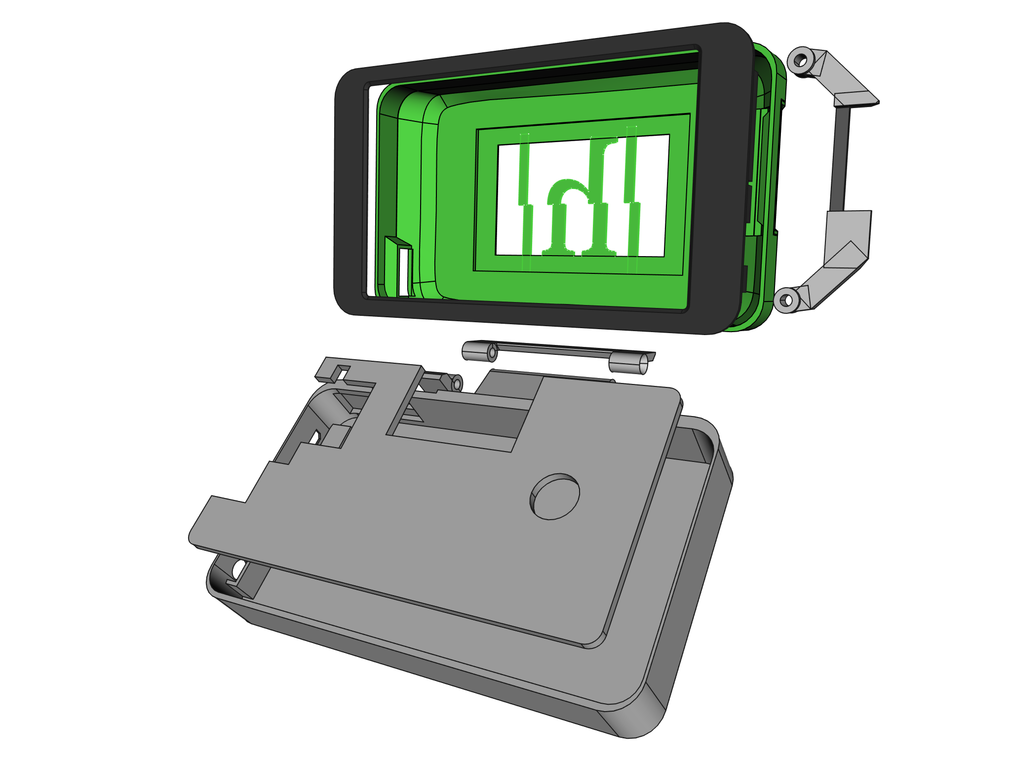
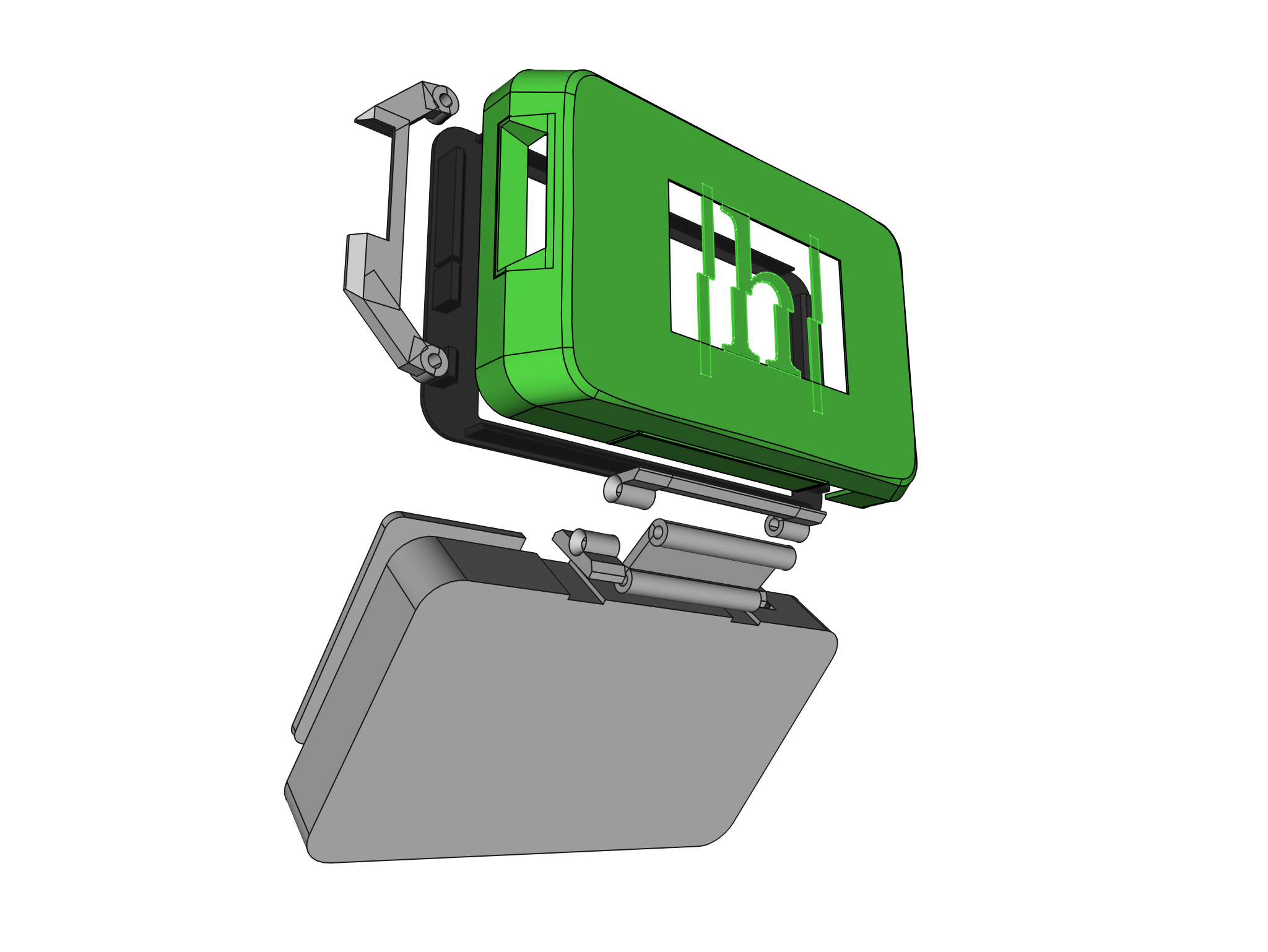
Enclosure
I built the 3D model of enclosure in FreeCad and 3D printed it on Anycubic i3 mega 3D printer. "Double" hinges allow the screen to fully open to "stand mode". FreeCad model and printable files are available in the git repository.
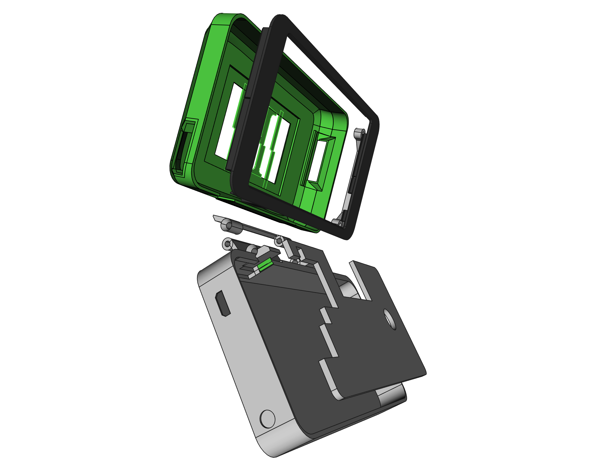
Final assembly
Final step was to assemble everything.
Software
There are few required software components:
- GUI
- RTC
- Arduino code (power management and GPIOs)
- display brightness
- battery status panel widget
- system service for handling power button
- other software
For the GUI I went with standard Raspbian distribution and replaced Openbox
windows manager with i3 as tiling WM better fits the
small screen. Here is a guide
on how to replace the window manager. However, one step is missing – at the
begining one needs to copy the /etc/xdg/lxsession to ~/.config/ to get
the default configuration.
Hyperpixel screen and RTC are installed by using the scripts linked on the
product pages. One thing to note: since the Hyperpixel display creates new I2C
bus (/dev/i2c-3) the PiRTC will not work by default but loading and enabling
the module in /etc/rc.local fixes this.
modprobe rtc-pcf8523
echo pcf8523 0x68 > /sys/class/i2c-adapter/i2c-3/new_device
Hyperpixel's backlight brightness can be adjusted using PWM on pin 19. I added
tools/brightness.py script which handles this and I'm triggering it from
keyboard using Win++ and Win+- key combinations.
I also assigned xdotool click 3 command to Win+, key combination which
enables me to use right click when needed (touch the screen to position the
cursor and hit the key combo to simulate right click).
In Arduino, available GPIOs are exposed as I2C registers. Check the
tools/arduino sketch in the repository for the details.
There is an LX panel widget in tools/lxpanel-battery. Currently
it only displays the battery voltage. At some point I'll have to record the
voltage during the discharge and convert it to percentage.
Besides that, I've installed standard Arduino GUI, platform IO and the open source FPGA toolchain. And of course, the Retropie.
Videos
Following YouTube videos show the process of Arduino programming (using platformIO), ULX3S FPGA board flashing and playing a game in emulator.
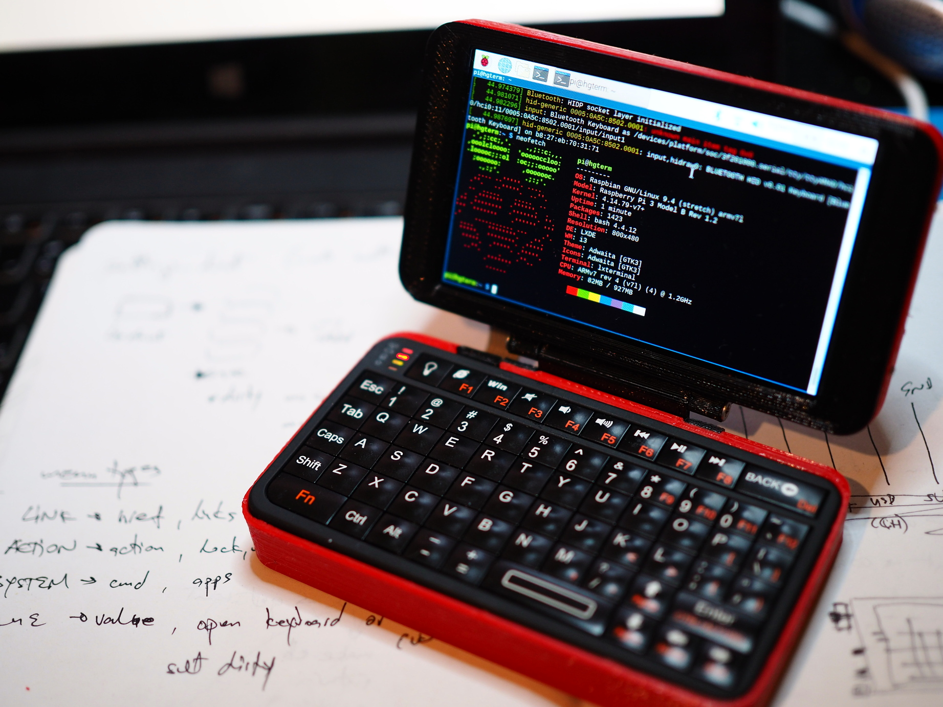
Summary
I'm very happy with the results. The device is quite thick and heavy (mostly due to the huge battery) but fits nicely in the hand. And the keyboard is much more usable than standard smartphone on-screen keyboard.
Used components:
- Raspberry Pi 3B
- Hyperpixel4
- PiRTC
- PowerBoost 1000C
- USB-serial
- Arduino Pro Mini
- Rii i5BT(518) Mini Bluetooth Wireless Keyboard
Repository with code and 3D models: https://bitbucket.org/igor_b/hgterm/