Table of Contents
Introduction
One of the often asked questions in the Raspberry Pi community is why there's a small lightning icon in the corner of the screen when the used power supply is more than capable of providing enough current. Lightning icon represents the undervoltage and shows up if the power supply voltage drops below 4.63±0.07V even for a very short amount of time.
The thing users (also me, a couple of years ago) usually don't think much about is the micro USB cable used for powering the system. I decided to do a quick set of measurements to show the effect of different cables to the supplied power. And, even though more and more devices use USB type C connectors, where cables are generally of higher quality, micro USB is still prevalent.
This doesn't apply just to Raspberry Pi but also to other cases when the load is powered using micro USB cable (for example mobile phone charging).
TLDR; for powering stuff or charging phones look for the micro USB cables with AWG20 (or thicker) power wires.
Theory
Theory behind this is quite simple but usually not something beginners and "normal" :) people think about. Basically, every wire has some amount of resistance (i.e. we can think of it as a resistor) and, according to Ohm's law, the voltage drop on it depends on the resistance and the value of the current passing through it. So, for signaling wires where there's no (significant) current passing through it doesn't really matter. But for power wires when few hundred milliamps (or few amps) are required it plays an important role: even if the resistance is small the voltage drop on it will be noticable when there's high current passing through. And voltage drop on the power cable is basically the wasted voltage which will not be at the load – if your power supply is 5.0V and the voltage drop on the cable is 0.3V then the device gets only 4.7V.
The resistance of the wire depends on the material, the cross-section (thickness) and the length – resistance increases with the length and decreases with cross-section. The way to reduce the voltage drop then is to reduce the resistance of the wire by using thicker and/or shorter wire. Most micro USB cables don't specify the wire gauge and use quite thin wires for all lines but some of the better ones do (and they usually use AWG20 for power wires).
Chargers
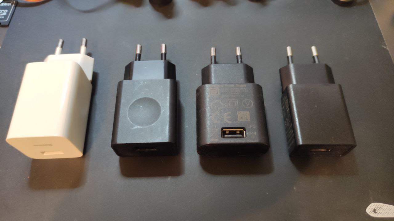
Mobile phone chargers are commonly used for powering stuff. There are various types but here I took four that I had laying around to check how their output voltage relates to current draw: Baseus FC67E (great power supply), charger from some Lenovo tablet and two no-name power supplies which came with some other hardware. I know I have few of 1.5A and 2A somewhere but couldn't find them now.
Interestingly enough I found that they are quite stable throughout the whole specified range (I really didn't expect them to be this good).
Testing method
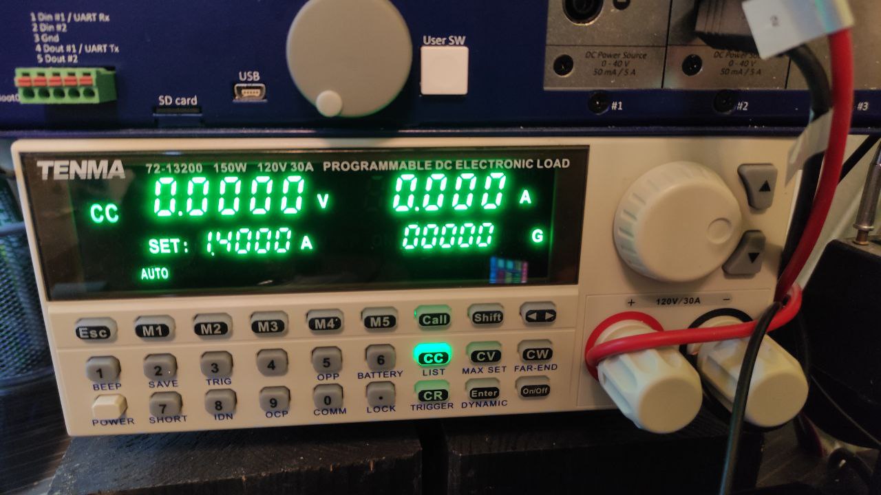
I used the TENMA 72-13200 electronic load connected directly to the male USB connector plugged into the supply. There is some voltage drop on the leads of the electronic load and the better way would be to connect a multimeter directly to the testing point but, since the measuring leads are quite thick I decided to ignore that in this case (actually I forgot for the first two chargers and then didn't want to repeat the measurements). Also, it doesn't matter too much as this is just to get the general overview.
Baseus FC67E (5V/3A, 9V/2.66A, 12V/2A)
| current | voltage |
|---|---|
| 0.0A (open) | 5.057V |
| 0.1A | 5.056V |
| 0.5A | 5.056V |
| 1.0A | 5.055V |
| 1.5A | 5.054V |
| 2.0A | 5.052V |
| 3.0A | 5.048V |
| 3.4A | 5.056V |
| 3.5A | 0V (protection) |
Lenovo 5V/1A
| current | voltage |
|---|---|
| 0.0A (open) | 4.986V |
| 0.1A | 5.073V |
| 0.5A | 5.061V |
| 1.0A | 5.068V |
| 1.5A | 5.025V |
| 1.7A | 5.008V |
| 1.8A | 0V (protection) |
No name 1 5V/1A
| current | voltage |
|---|---|
| 0.0A (open) | 4.870V |
| 0.1A | 4.929V |
| 0.5A | 4.992V |
| 1.0A | 5.069V (rising from 5.06 over 5.08) |
| 1.1A | 0V (protection) |
No name 2 5V/1A
| current | voltage |
|---|---|
| 0.0A (open) | 5.075V |
| 0.1A | 4.960V |
| 0.5A | 5.073V |
| 1.0A | 5.178V |
| 1.2A | 5.240V |
| 1.3A | 4.335V |
| 1.4A | 0V (protection) |
Chargers summary
I didn't really expect the two no name chargers to cover the whole nominal current range without voltage drop. Also, the Lenovo charger goes above the rating (maybe not for too long – I tested each point only for 10-20 seconds). But the conclusion is that those kind of power supplies are quite stable (this is just the static test and I haven't tested the dynamic characteristics).
Cables
I grabbed few of the cables I had in the box with cables and one which I usually use.
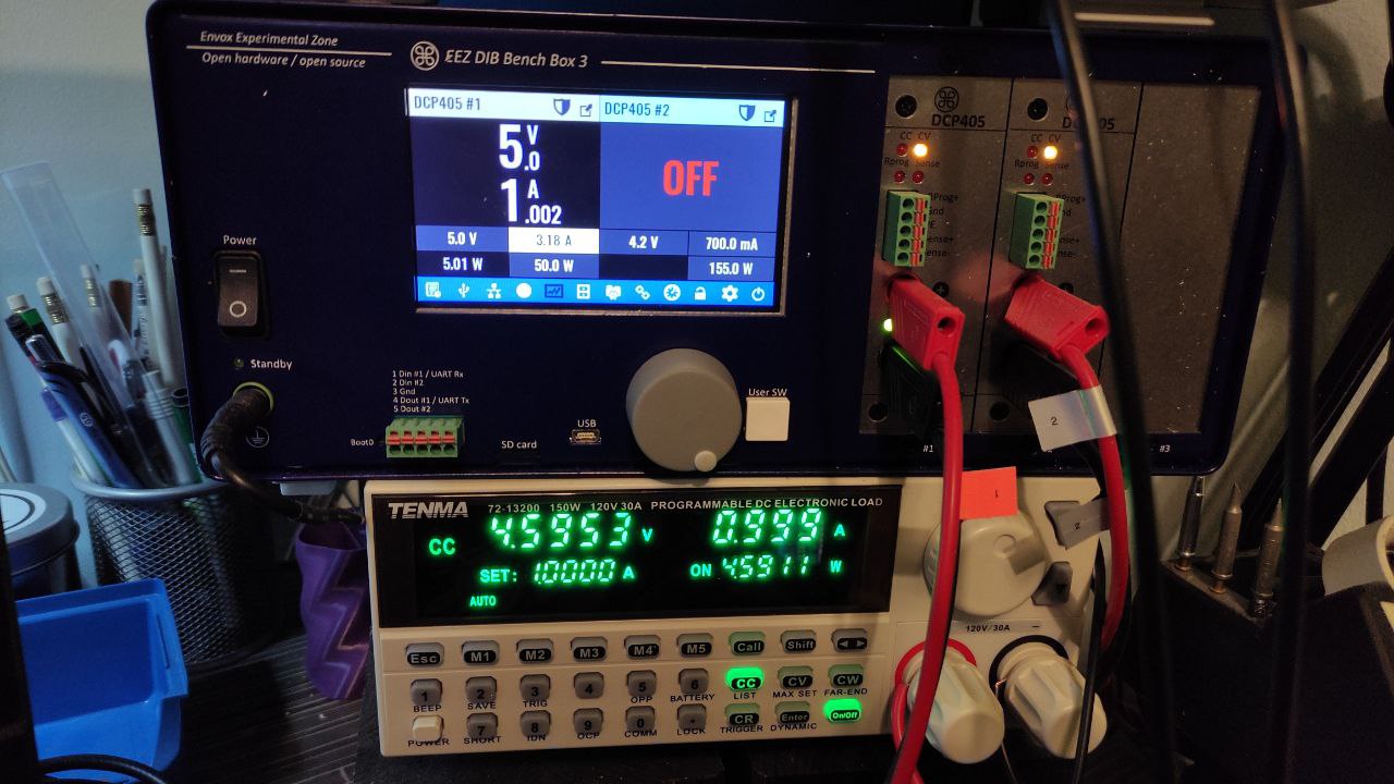
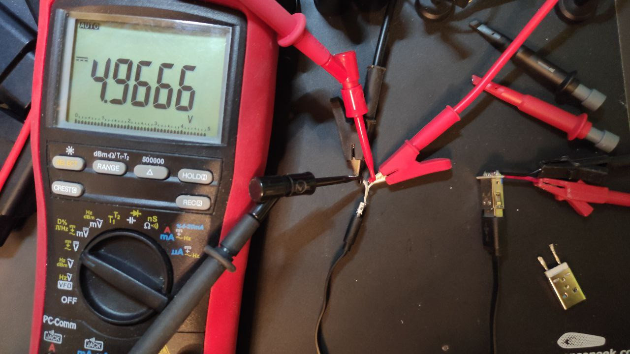
To test the cable I used my beloved Envox BB3 power supply as an input, TENMA for load but this time I also connected the multimeter (Brymen BM869S) to the test point to get the accurate measurements. BB3 output is connected to female USB A connector, TENMA+multimeter to female micro USB connector and the cable under test is plugged between the connectors.
There were four cables under the test:
- generic short (25cm) cable which came with some powerbank if I remember correctly)
- generic 90cm cable which came with some dev board
- generic 200cm cable which I bought many years ago in order to power the Pi 1 :)
- Tronsmart 180cm micro USB cable (20AWG power lines) – Anker also has some similar ones
This test is missing another good option: charging cable which comes with smartphone (especially with the ones which support quick charging). The one that I have (with micro USB connector) is currently in use so I couldn't measure it but it should be a ok as it's currently powering one Raspberry Pi without undervoltage warning.
generic 25cm micro USB cable
| current through cable | input voltage | output voltage |
|---|---|---|
| 0.1A | 5.0V | 4.962V |
| 0.5A | 5.0V | 4.821V |
| 1.0A | 5.0V | 4.638V |
| 2.0A | 5.0V | 4.272V |
| 3.0A | 5.0V | 3.903V |
generic 90cm micro USB cable
| current through cable | input voltage | output voltage |
|---|---|---|
| 0.1A | 5.0V | 4.936V |
| 0.5A | 5.0V | 4.672V |
| 1.0A | 5.0V | 4.341V |
| 2.0A | 5.0V | 3.672V |
| 3.0A | 5.0V | 2.978V |
generic 200cm micro USB cable
| current through cable | input voltage | output voltage |
|---|---|---|
| 0.1A | 5.0V | 4.892V |
| 0.5A | 5.0V | 4.454V |
| 1.0A | 5.0V | 3.908V |
| 2.0A | 5.0V | 2.809V |
| 3.0A | 5.0V | 1.665V |
Tronsmart 180cm micro USB cable (20AWG power lines)
| current through cable | input voltage | output voltage |
|---|---|---|
| 0.1A | 5.0V | 4.963V |
| 0.5A | 5.0V | 4.803V |
| 1.0A | 5.0V | 4.604V |
| 2.0A | 5.0V | 4.209V |
| 3.0A | 5.0V | 3.811V |
In this case if we bump the voltage to 5.2V (like the official RPi power supply does) we get 4.73V at 1.2A and 4.614V at 1.5A which makes it pretty good option for powering the RPi3/4 when the longer cable is needed.
Summary
It turns out phone chargers, even no-name ones, are quite stable across the whole specified current range (based on four tested units :)). However, USB cables, as we can see from the measured voltage drop on them, greatly affect the power transfer to the load. First three tested ones are some cheap/generic ones and shouldn't really be used for reliably powering the power hungry stuff. Cables which come with smartphones are usually good so they should be used unless longer cables are needed or better one is available.
It's not easy to find good micro USB cable as most manufacturers don't specify the used wire gauge. If there's possibility to choose, AWG20 or thicker gauge (i.e. lower number) for power lines seems to be good option.
So, considering that RPi (without peripherals) at full load takes up to 1A (3/3B/3B+) or up to 1.5A (pi4), if the lightning icon appears (or dmesg reports undervoltage warning) it's probably not the issue with the power supply but with the cable.
EDIT: A better charger analysis would be to also include the shape of the voltage at the output of the charger as, even though it can provide enough current, the waveform can be very bad.