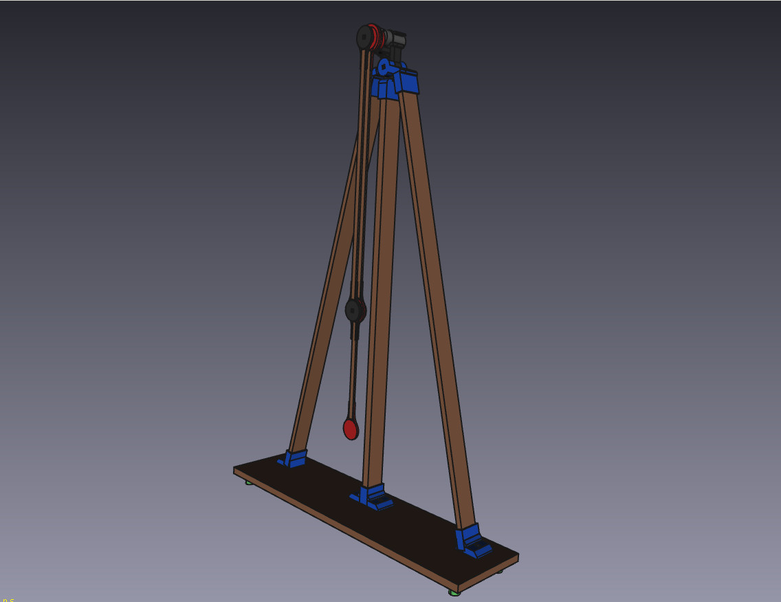
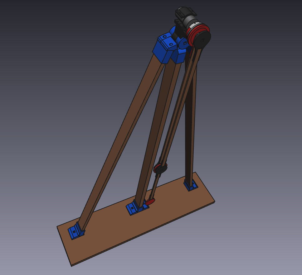
KLAATNO (klatno is Croatian word for pendulum) is a powered double pendulum mechanical installation.
Double pendulum is one of the simplest dynamical systems which exhibits chaotic behavior. I always wanted to build one and find a way to make it powered and I finally built it for Radiona's Robotika Mechanika exhibition.
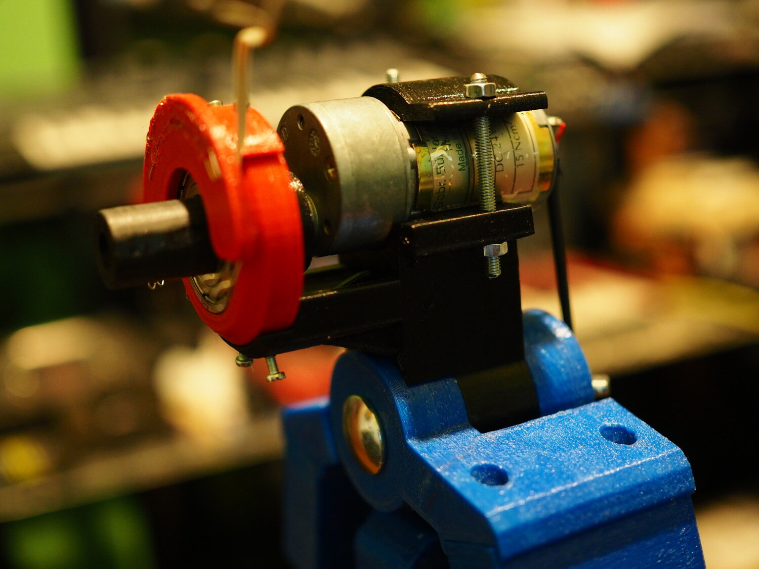
The systems consists of two pendulums attached one to another where the "main" pendulum is powered using DC brushed motor. The main idea is to track the speed and direction of the main pendulum and "assist" it with motor. I had a nice 24V DC motor lying around (thanks to Goran Mahovlic who gave it to me for one project but I never used it) and decided to use it for this. It's not ideal as it has gearbox which prevents the free motion of the rod when the forces are small but I wanted to test if the idea would work and made some 3D models and later was too lazy to modify everything for some other motor.
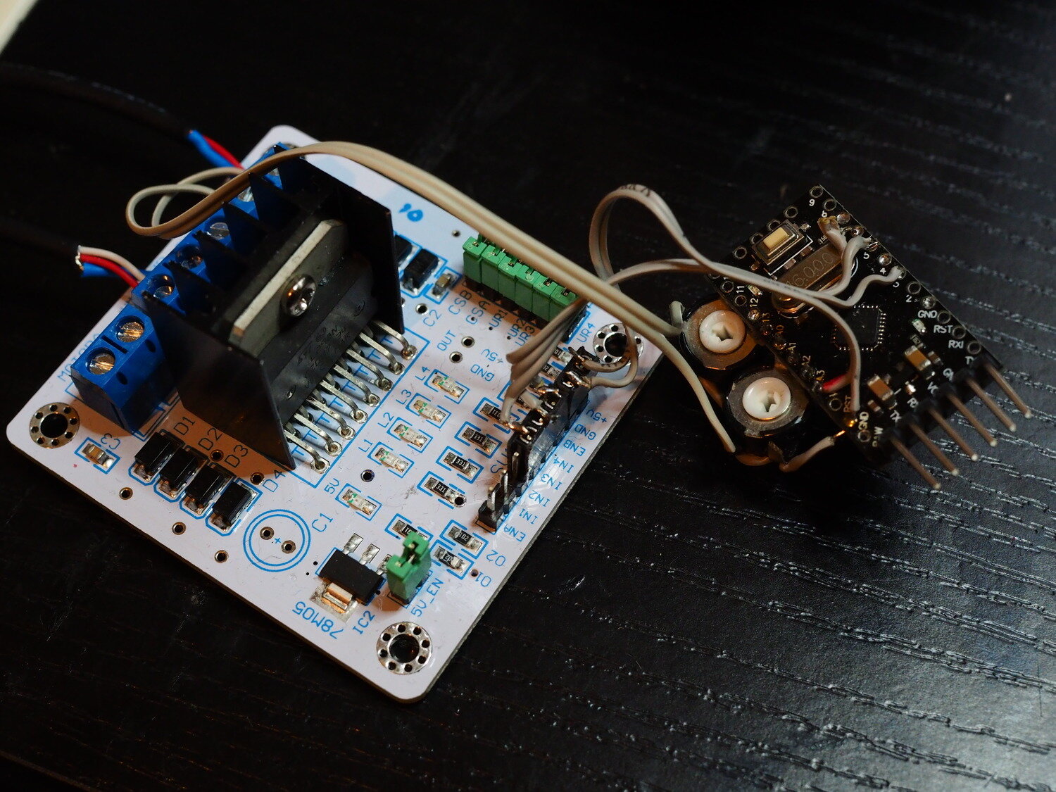
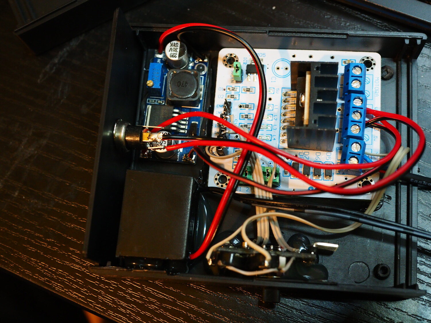
The speed and direction is tracked by measuring motor's back EMF – a voltage induced on its terminals when it's in motion. I used Arduino Pro Mini clone board (as for most simple projects) and wired it to measure the BEMF using two analog inputs: one for positive and one for negative voltage. A wire from each of the two motor's terminals goes through the resistor divider (I used 50k trimpots to enable adjusting the gain) into each analog input. Better way would be to add clamping Schottky diodes to both inputs since the voltage (especially negative one) exceeds AVR's input limits, but as the series resistance is quite high the internal diodes should do just fine. There's an additional potentiometer to adjust the gain of the motor's feedback.
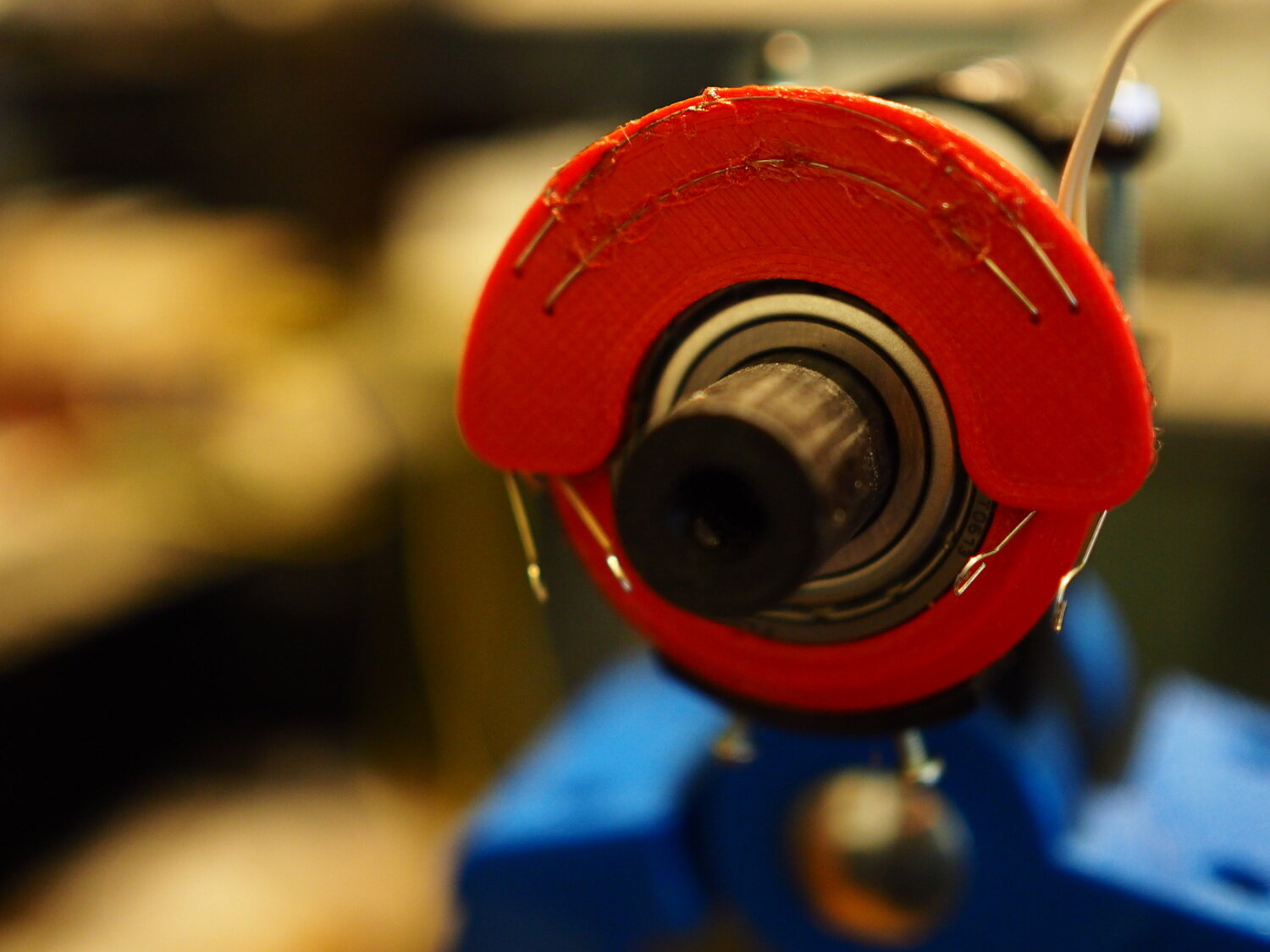
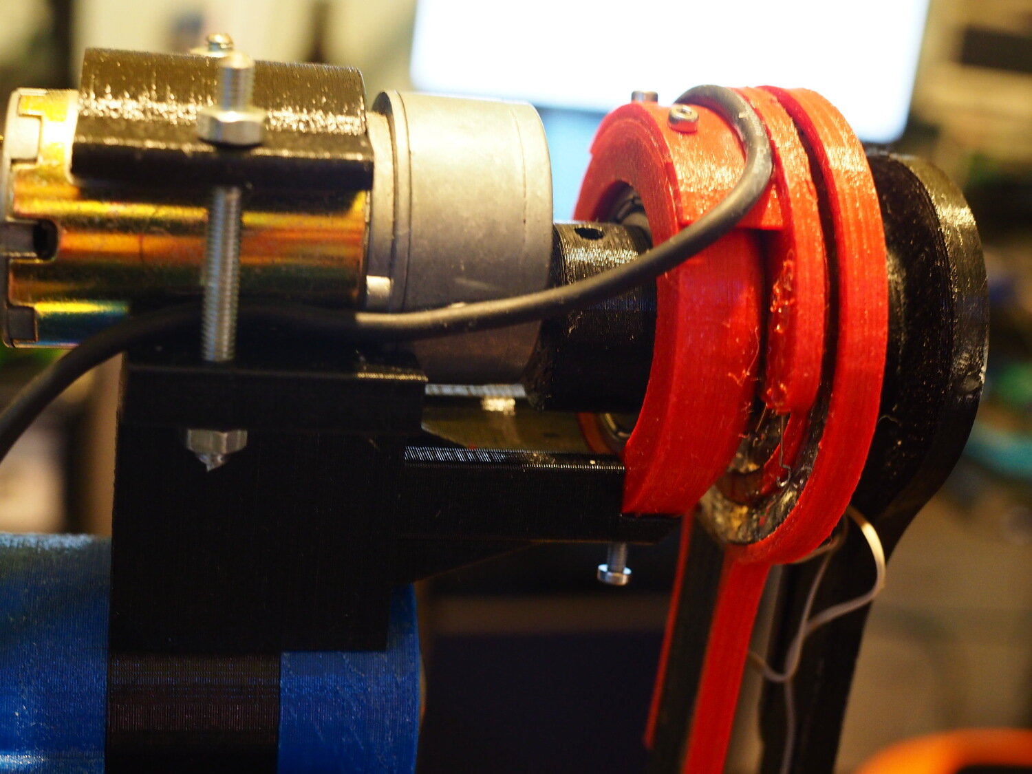
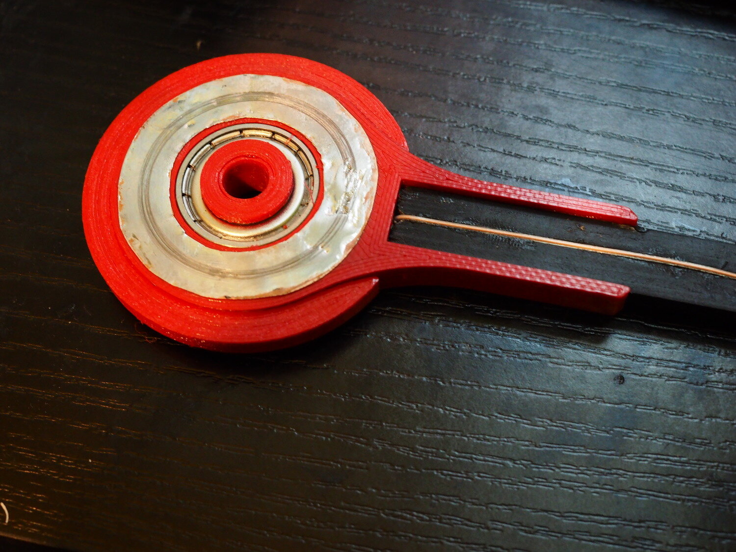
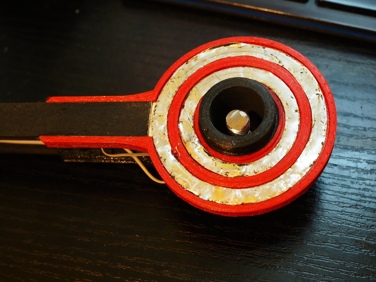
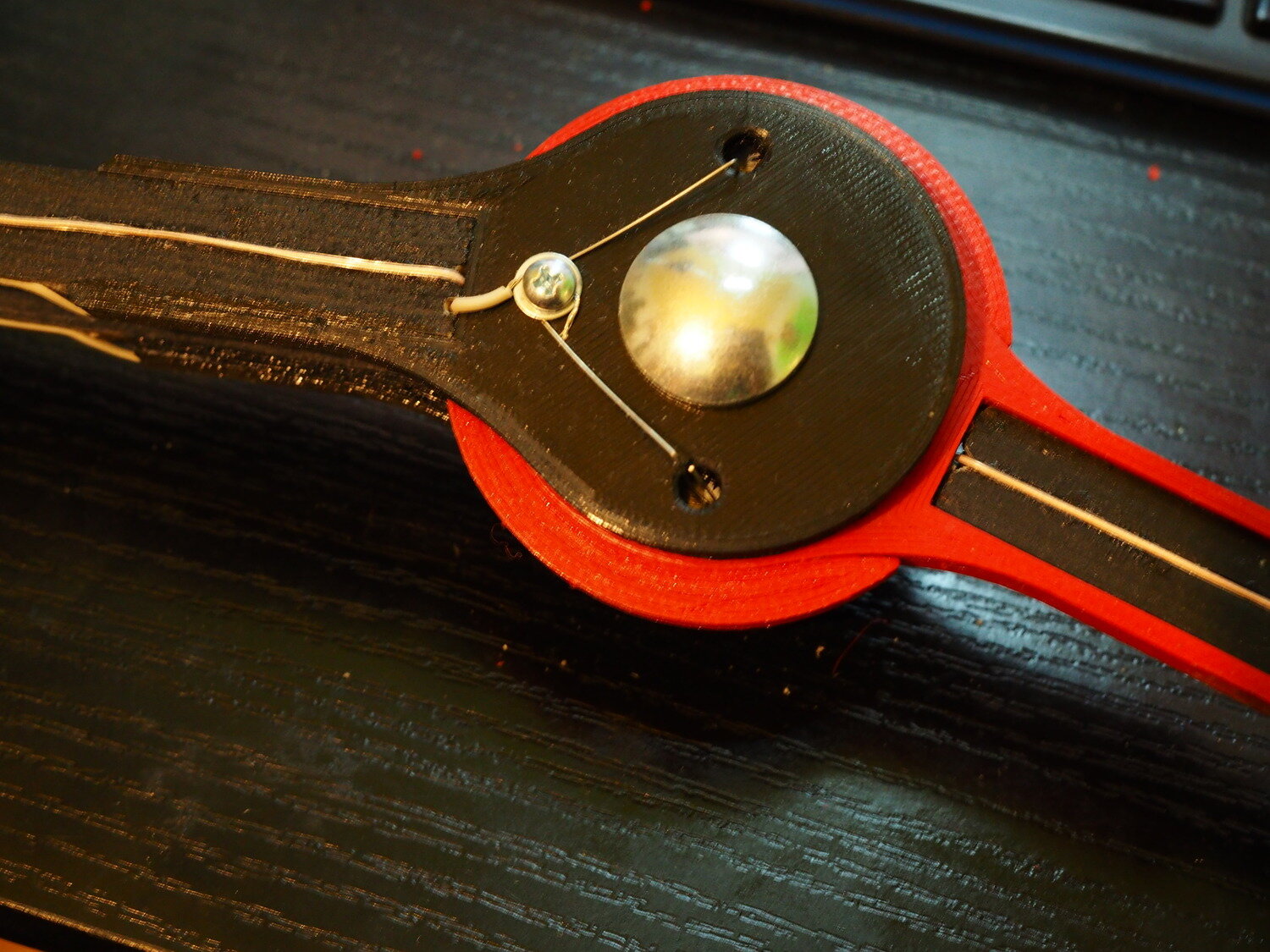
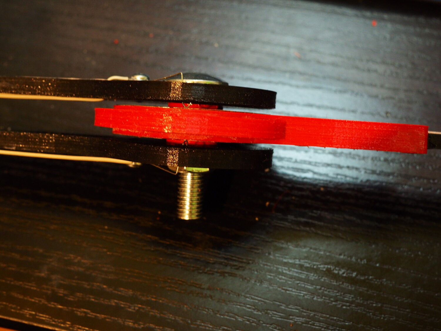
Additionally I wanted it to look "cool" (depending on one's definition of "cool") and wanted to add some decorative lighting so I went with EL wire. This proved to be quite a challenge as both pendulum rods should rotate freely and I need to somehow power the EL wire. The solution was to use (DIY) slip-rings made from thin copper sheet and a piece of elastic wire as a slider (G string from the electric guitar in this case). So even though I added ball bearings to the joints to reduce the friction, the slip ring increased. Later I got an idea to use ball bearing as a slip-ring for one wire and use this home-made solution just for the other wire but haven't tried it. Using thinner wire would also help to reduce the friction (I plan to do this at some point.
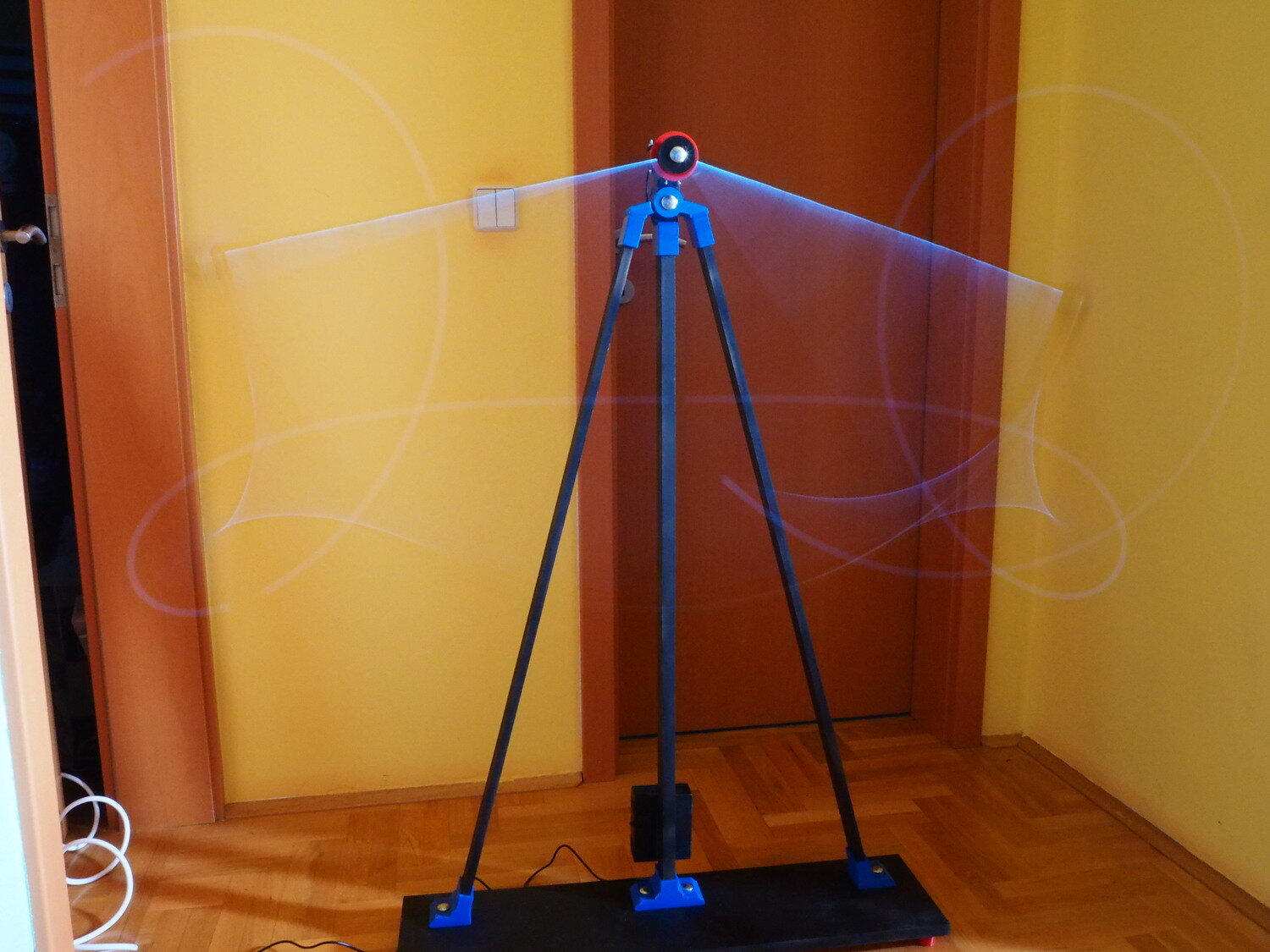
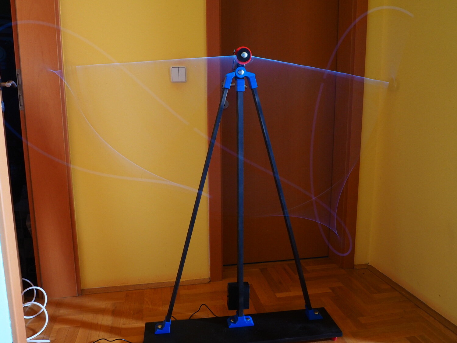
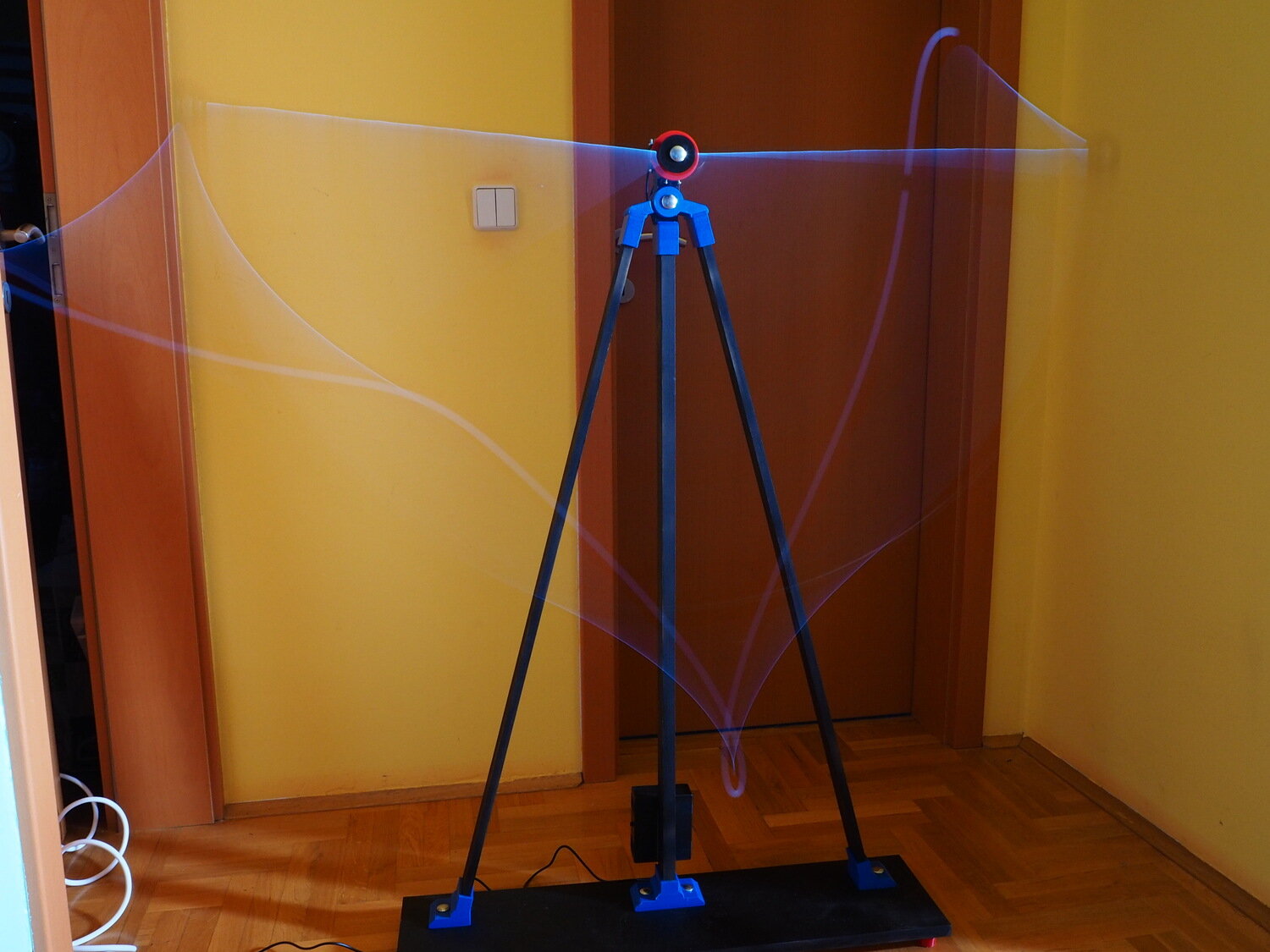
By adjusting the gain of the motor assistance, the system can go from periodic motion when set low to full rotation when set too high. Most interesting effect is just below the rotation threshold.
Source code and the 3D model of the whole system can be found at https://bitbucket.org/igor_b/klaatno/