Table of Contents
Introduction
This year I got the awesome opportunity to design the electronic badge for the DORS/CLUC 2024 conference. DORS/CLUC (Open system days / Croatian Linux Users' Conference) is largest (and one of the oldest ones) regional open source developer's conference. It is held annually in Zagreb, Croatia.
This is the first time the conference has an electronic badge, and I wanted to make it special. The rest of the organization team accepted most of my suggestions and I'm very happy with the final result.
![]()
The instructions for the badge are available on the https://www.dorscluc.org/badge/. The web UI for the badge configuration is available at https://f.hyperglitch.com/dc2024.
The slides from the talk about the badge are available at https://f.hyperglitch.com/20240516_badger_badger_dc2004.pdf.
Design
The overall shape, design and graphics are done by the amazing Lucijana Dujić Rastić from Studio Utopia. She is also the creator of the conference logo.
The badge is designed to be worn as a necklace, and it is powered by two AA batteries.
![]()
Features
Most prominent part of the badge (besides the well-known penguin shape of the conference logo) is the 2.66" monochromatic e-paper display. The display contains a part for the user-configurable text and a part for the quest-like social game.
Each badge periodically (every 90 seconds) transmits an unique code through IR. The badge also listens for the codes from other badges. When badge receives a new, previously unseen code, it will increase the total badge count on the display. Additionally, if the sender badge is one of the 12 "special" ones (belonging to some speakers, organizers), the receiving badge will unlock/unhide one of the twelve parts of the hidden image. The final goal is to hang out with other participants in order to unlock the whole image and increase the total badge count.
The user-configurable part of the screen can be configured using a special web-based interface which uses the whole page color change (blinking/flashing) in order to encode the configuration. The badge has an ambient light sensor which is used to detect the intensity of the light. If the user puts the badge (i.e. the sensor) in front of the web based interface, it will receive the configuration and update the display.
The badge also has an array of blue LEDs blinking in different patterns. The blinking pattern can be changed by pressing on the penguin's beak (touch sensor).
Hardware
The badge is based on the STM32L431 microcontroller. The e-paper display is Waveshare 2.66" monochromatic display (raw panel) connected to the SPI port with the driving circuitry on the PCB. The rest of the schematic is pretty straightforward - ambient light sensor, IR transmitter and receiver, touch sensor, and a bunch of blue LEDs connected in matrix.
![]()
The badge also contains a touch key (penguin's beak) which is used to cycle through the LED blinking patterns. The touch key is implemented by enabling the pull-up resistor on the GPIO pin (to charge the capacitor C24) and then switching the pin to analog input mode measuring the time it takes for the capacitor to discharge.
First revision of the board didn't have the voltage supervisor and, during the firmware development, I had many occasions where the badge wouldn't properly boot. After adding the voltage supervisor those issues were gone. Also, the badge contains 32.768kHz crystal for the RTC but the internal HSI clock is used.
Firmware
The firmware is written in C using the STM32CubeIDE. E-paper driver code was taken from the Waveshare's GitHub repository. The rest of the code is written from scratch.
For data transmission (both IR and light-based) I used Manchester encoding on top of the custom predefined protocol. Manchester encoding is a self-clocking signal with equal number of high and low transitions which helps to recover the clock signal on the receiver side.
The main issues I had during the firmware development were related to transmitting the data over the light sensor, mainly because of the different characteristics of the displays on different smartphones. The badge is continuously sampling the light sensor and the detection algorithm works in a way to detect the crossing of some fixed threshold and then going back to find the exact point where the signal started rising or falling. This also required to cover some special cases when the noise is present so the rising/falling edge is not completely monotonic (I allowed for one outlier sample). In the end, it worked great on some phones and not so good on some others. Slowing down the transmission speed helped in some cases (disabling fast mode on the we UI).
![]()
![]()
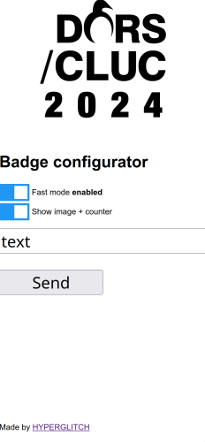
Web configuration
The configuration interface is a simple static web page with some JavaScript. Upon setting the text and selecting the options, the page will show a full screen color change (blinking) which is then detected by the badge.
It also contains an option to hide the "quest" part of the screen (the part with the total badge count and the hidden image).
Open hardware
Complete design files including the KiCad project, firmware source code, web-based configuration page and the 3D model for the programming jig are available in the GitLab repository: https://gitlab.com/hyperglitch/dc2024badge. The repository also contains the scripts (using KiKit) to generate the production panels and the production data for direct upload to JLCPCB.
The hardware is released under the CERN-OHL-P-2.0 license and the firmware under the MIT license.
The device is certified as an open source hardware under the OSHWA certification program with a mark HR000116.