Device
Device consists of an arduino, serial LCD driver + LCD display, a nice box and a few keys and knobs. Wiring diagram is pictured on the following image (click it for larger version).
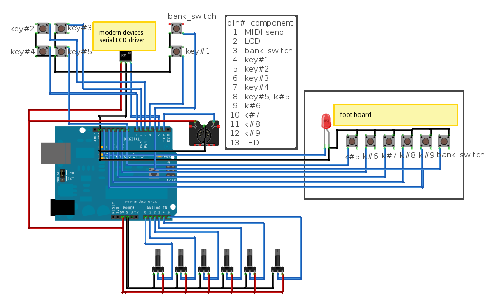
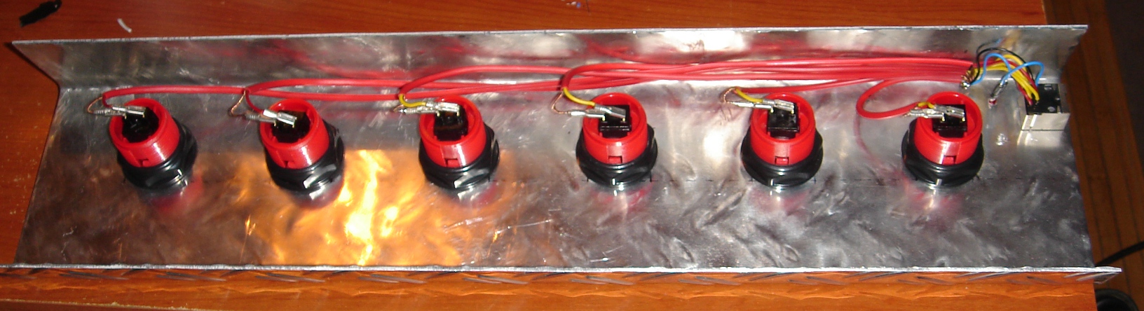
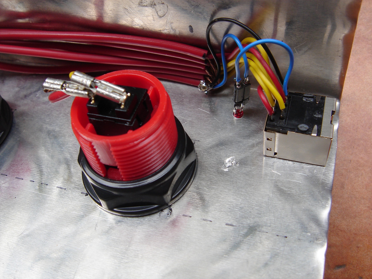
I used a RJ-45 connectors (network cable connectors) to connect main device with footboard. As you can see from the wiring diagram, there are a lot of wires to be connected and, since I wanted a nice little enclosure for the device, it gets pretty ugly when trying to fit everything in :). Also, I think I wired the MIDI connector wrong, but it is not used in current implementation so it doesn't matter.

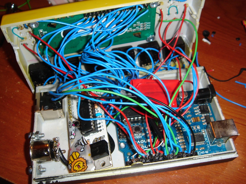
I really don't know how I managed to get everything inside (advice: if you want to make this use bigger enclosure). I also didn't had any electrical tape so you can see tape with lion and zebras used for isolation purposes.
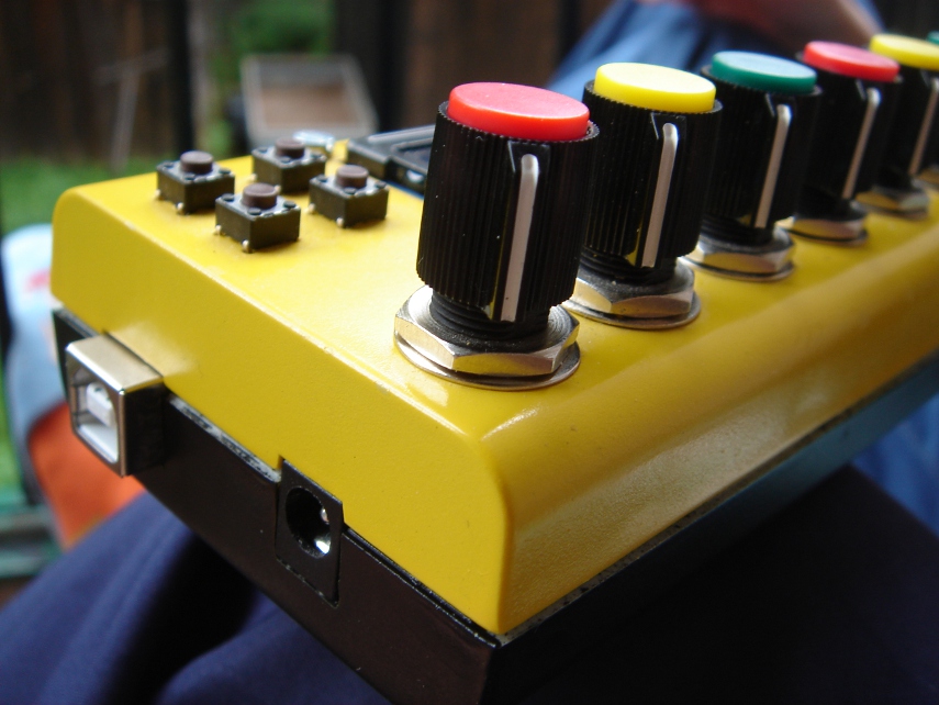
At the end (next morning) I somehow managed to close the box so here is the final result:
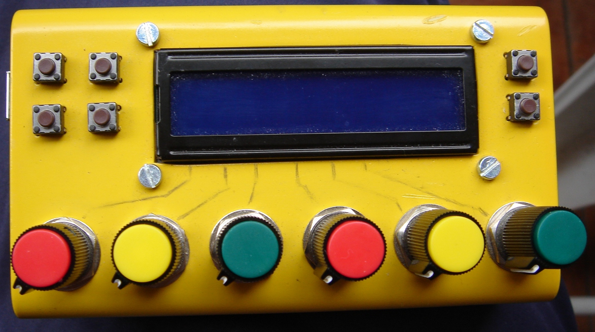
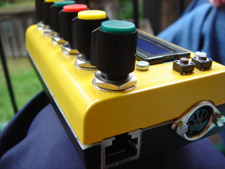
LCD display on device currently is used only to display simple message and to show current bank (asterisk in first row means bank 1 and asterisk in second row means bank 2). Arduino code for the device can be downloaded from http://f.hyperglitch.com/ctrlr/ctrlr.pde.
Computer software to give some kind of functionality to this device can be found here.
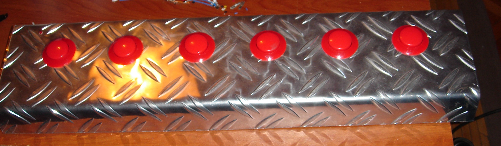
Footboard
Since the first idea was this to be a foot controller, a footboard is pretty important. Biggest problem were keys. There are pretty good keys made especially for this kind of things but they are usually expensive and hard to find. So my idea was to find an old poker or arcade machine because that keys are made to be hard to break. Accidentally I found this and immediately ordered needed+replacement buttons.
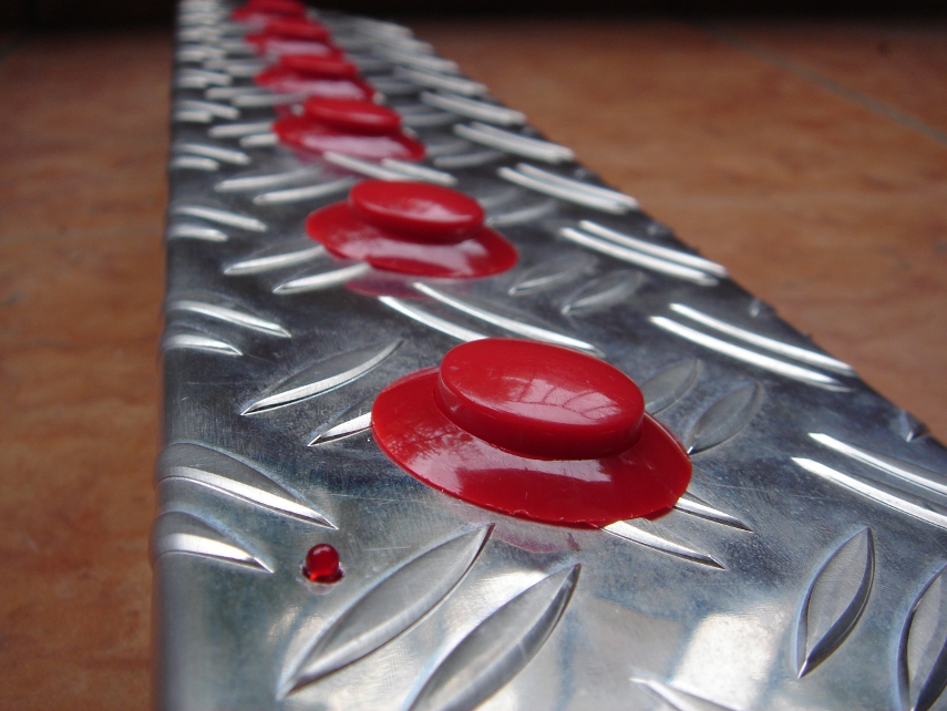
So, this is the result: