Some time ago, as a fun project, I made a lightsaber replica with sound and light effects. The lightsaber is based on the ESP32 microcontroller and uses a gyroscope to detect motion and activate the sound.
The original article was published on https://hackaday.io/project/188010-darth-vaders-lightsaber on 2022/10/27. The article is published here for archival purposes.
Table of Contents
Introduction
The goal is to make a replica of the Darth Vader's lightsaber which will produce sound and change blade color depending on the motion.
Main sections:
- MCU
- sound output
- light
- sensor
- light
- case + hardware
I will go through each of these in the following steps.
The device should consume no power when not in use (except for the minimal consumption of the battery monitor) and should have only a pushbutton as a control.
One of the goals is to use components I already have (luckily I have a lot of stuff around :)). That's why for the motion sensor I went with ITG3200 gyroscope as I had one on the breakout board laying around.
The git repository containing the code, 3D models and schematics can be found here: https://bitbucket.org/igor_b/lightsaber/src/master/
Sound output
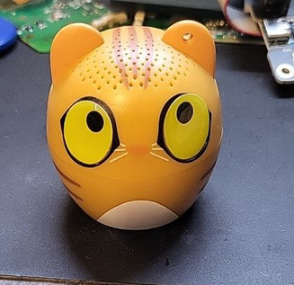
For sound output I needed a speaker and an amplifier. Since I didn't have any speakers with the right dimensions I found the smallest/cheapest bluetooth speaker in a local shop which turned out to be of a perfect size with a cost of slightly below 10€ (there are probably much cheaper things available on AliExpress but I wanted to get it without waiting). It's iDance keychain speaker. Unfortunately it doesn't have AUX input so some hacking is in order.
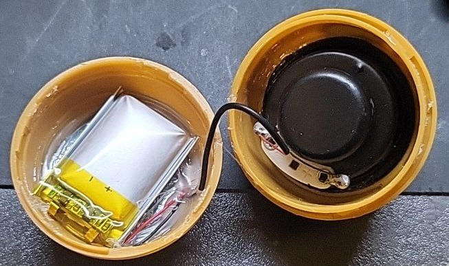
The speaker is (hot) glued so some heat is needed to open it.
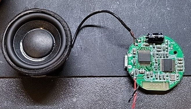
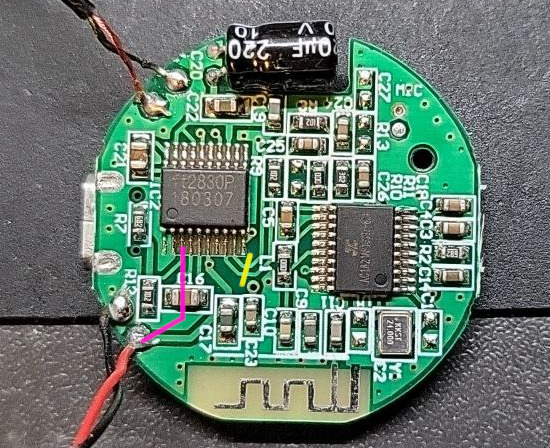
The PCB contains MCU+BT and a small power amplifier. The amplifier (FT2820) is connected directly to battery but the enable pin is controlled from MCU. The datasheet contains a lot of details. So, a quick test proved that just connecting the power and pulling the amplifier's EN pin high is enough to get the sound output with the MCU being powered off. The EN pin is pin number 3 and sound + and - inputs are pins 8 and 9 (yellow line). The two traces to sound input pins need to be cut and the pin 3 needs to be connected to input power (purple line) - I don't have the closeup picture of the finished work so I just drew the lines.
To properly get the sound signal into the amplifier it needs to be AC coupled so capacitors are needed in line with the input.
Power supply
The goal is to have one pushbutton control the device. This creates a slight issue for the power-off animation+sound as it needs to run after the button has been released. So, we need a latching circuit which will detect when the button has been released and then run the poweroff animation+sound and then completely power off the device.
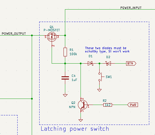
For this we will use the P-channel MOSFET Q1 (pretty much any with apropriate gate threshold and current capability) as the main switch. The R1 keeps it open. Pressing the pushbutton will connect the gate to GND and cause the MOSFET to start conducting and power the rest of the circuit. If the pushbutton is released the MOSFET will stop conducting and cut the power. That's why we also have Q2 which can connect the MOSFET gate to GND if activated from the main MCU using the PWR pin. So the main MCU needs to set the PWR pin high to keep the current flowing (even when the button is released) until it does all of the poweroff stuff and then clear the PWR pin which will cut the power to the whole device.
To be able to also sense the status of the pushbutton from the MCU (and since the MCU runs on 3.3V and the battery can go up to 4.2V), two Schottky diodes D1 and D2 are needed. The BTN pin needs to be pulled-up on the MCU side (using internal pull-up resistor). In this case those two diodes need to be Schottly type (with the forward voltage of around 0.15V) as the standard Si diodes will not work.
For the MOSFET I used the IRF9332TRPBF (since I had it) and for Q2 I used BC548 but almost any other NPN bipolar transistor with similar characteristics would work.
3D model
The body of the lightsaber is modeled from scratch in FreeCAD based on the model I've found online and printed in silver and black colors with a few decorative screws.
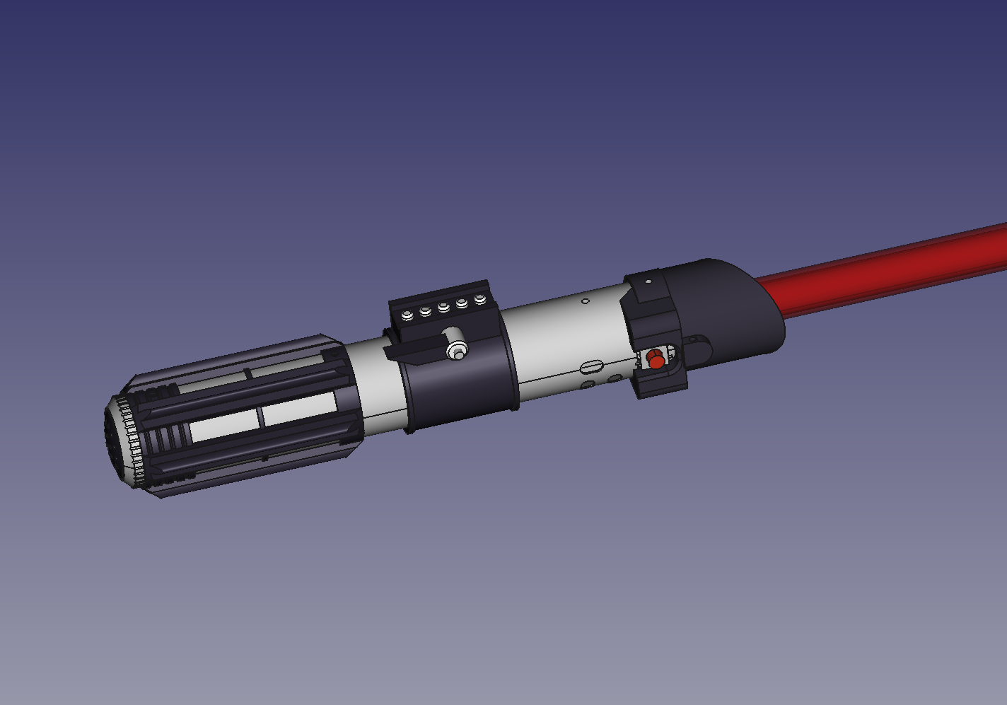
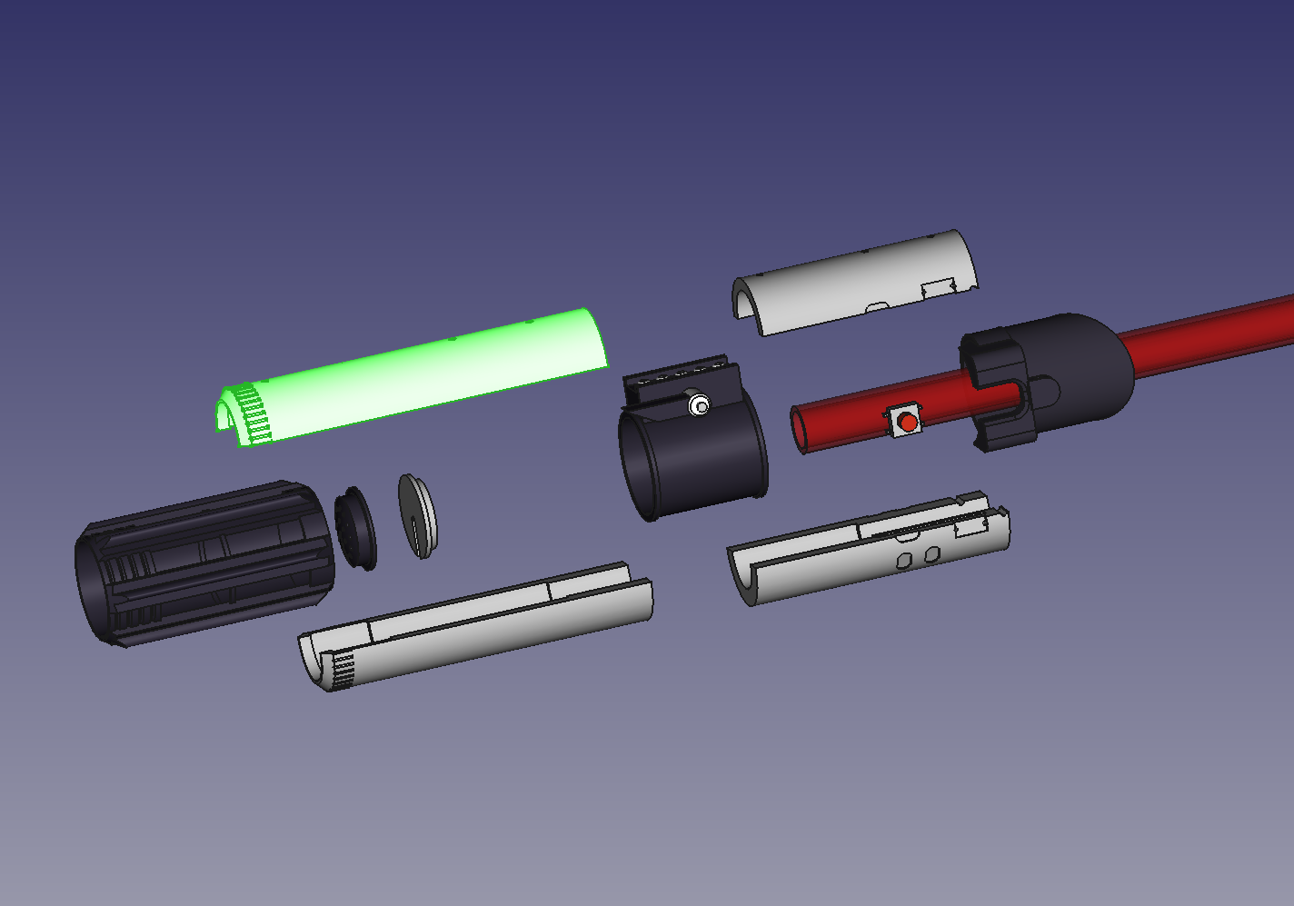
Main body "tube" is printed in four parts. The bottom part would be better if printed in one piece but it didn't fit my 3D printer so I glued it afterwards. Also I got some "metallic" filament for the grey parts as they should be chromed but it turned out pretty mate grey...
The FreeCAD and STL files can be found in the git repository.
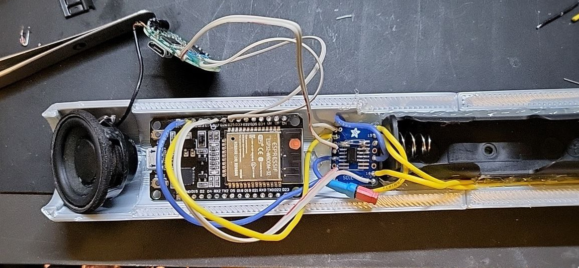
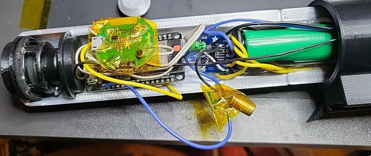
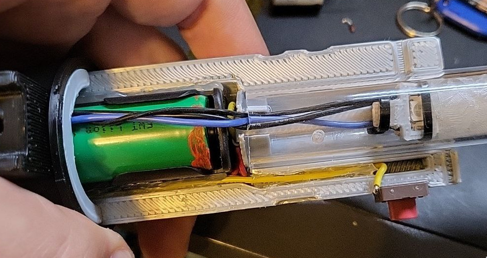
Mounting/connecting everything
I did everything as I went so there wasn't too much planning. That resulted in the insides not looking very pretty. The connection schematic in higher resolution can be found in the git repository.
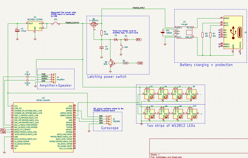
The charger I had has micro-USB connector. I also had small USB-C breakouts so I mounted the charger under the battery holder and added USB-C connector for charging input (it didn't had 5.1k resistor on CC lines so I had to add that to be able to get any power from USB port but I glued the small board in place and don't have the picture of the resistor hack). The LED strips and the power amplifier are powered directly from the power line and the MCU and sensor are powered from the additional 3.3V LDO.
The first iteration used the LDO on the ESP32 dev board to get 3.3V from the battery voltage but it has too high dropout voltage so even when the battery is at 50% charge, when the sound kicks in the voltage dropped enough to cause the ESP32 to reset. Adding the external LDO (I had MIC5503-3.3V which can provide up to 300mA and with 150mA dropout voltage) with lower dropout voltage (and a chunky capacitor just in case) solved that issue.
The gyroscope board had pads for I2C pullup resistors so I added them there.
The AC coupling capacitors (small 0603 ones) for the sound output are soldered directly to the ESP32 board pins. Also, since we're sending the single-ended audio signal, only one (AUDIO-) signal should be sent to the amplifier with the other grounded through the capacitor but that was solved by not using the other DAC output.
I added a jumper to be able to disconnect the ESP32 board from the battery while it's connected to the USB power for programming.
Firmware
This project is using ESP32 board and the code is written using esp32-arduino. Here I'll add few notes about required libraries and general functionality.
For the blade I used WS2812 RGB LED strip with 144 LEDs/m. It is supported by the great FastLED library which is available to install using Arduino's built in Library Manager. For the motion sensing I went with ITG3200 gyroscope since I had it but pretty much any motion sensor (gyroscope or accelerometer) will do with slight code adjustments. Gyroscope is better for this since it outputs the angular velocity directly which is what we need here (accelerometer's output would have to be integrated and filtered to get the same results). For ITG3200 I used the Grove 3-Axis Digital Gyro library available through Library Manager. In this case I also shorted two solder bridges on the gyro board: one to select the internal clock and another one to select the other I2C address (as the other one was default with this library).
For the sound output using the ESP32's built in DAC (which isn't really good BTW, but it works ok for this) I used awesome XTronical sound library. It's not available from Library Manager and it has to be installed manually following the instructions on the page: https://www.xtronical.com/the-dacaudio-library-download-and-installation/. I also tried using ESP8266Audio library which worked but the compilation times were too slow.
In my case there was an error when trying to compile any example using the XTronical library. I found that there was a solution here: https://github.com/WeekendWarrior1/XTronical_XT_DAC_Audio_Mirror/issues/1 - basically, #include "soc/rtc_io_reg.h" needs to be added on top of the XT_DAC_Audio.cpp file inside the installed library's folder.
I used the sounds from https://freesound.org/people/joe93barlow/packs/5968/ and converted them to the required format.
When the button is pressed and ESP32 board is powered up, first thing needed is to set the power pins to detect the state of the button and to keep the power even if the button is released. Then the starting sound is played together with startup animation. The idling sound is also started here and set to play in the loop. The main loop takes the X, Y and Z values from the gyro, calculates the magnitude of it and uses that value for adjusting the light - I've found some threshold values which seemed ok and mapped that usable range of values to color change. The base color is red but the blue and green channels are added in proportion to the motion intensity so the blade gets brighter with faster motion. Also, when the motion magnitude crosses a defined threshold the swing sound is triggered. In addition to that I also added a slow oscillating brightness change to the blade when idle.
When the code detects that the button has been released (with 100ms of software debounce period) it triggers the poweroff sound, runs the animation and then completely powers off the device.
Blade
I needed a way to get a nice diffused blade so that the individual LEDs aren't (that) visible - that's also the reason I went with 144 LEDs/m strip instead of more common 60LEDs/m. Also, I wanted to avoid putting the diffuser on the outer side of the blade to get the nice shiny surface.
Main component is 20mm/16mm acrylic tube. Ideally I wanted something which would diffuse the light along the length of the blade (some sort of lenticular duffuser) but couldn't find anything like that which would be easy to obtain. In the end I found the textured acrylic foil used for blurring/diffusing the windows. Since it had to go inside the acrylic tube but still had to be at some distance from the LEDs to actually diffuse the light, I wrapped two layers of it on some tube I had (to get the external diameter of slightly more than 15mm), put it inside the tube and put the LED strip inside (it wasn't an easy thing to do, especially considering that the diffusion foil has adhesive on one side).
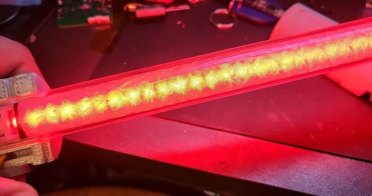
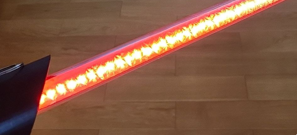
The light diffusion isn't the best since the LEDs are too close to the foil, but it looks quite nice.